For the homebrew computer, I will need to implement SPI and I2C support to allow the FPGA to communicate with the LCD screen and ADC. To get an idea of how to go about this, I turned to tutorials uploaded on Youtube. But before getting in deep, I started by learning a simpler protocol, asynchronous serial communication.
The protocol uses two wires to handle communication between devices. One wire is used for sending data (TX), and the other for receiving (RX). See this diagram from Sparkfun:
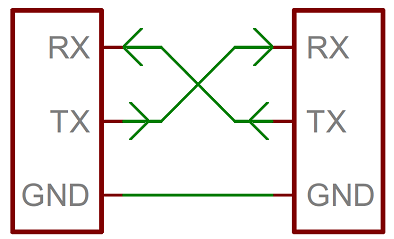
Quoting Sparkfun, the device used to create and read the data packets sent over these wires is called a Universal asynchronous receiver transmitter (UART). See the article for a great breakdown of how it all works.
I followed these two tutorials on Youtube (Nandland and Toni T800) to learn how to program an FPGA to act as a UART.
The Setup
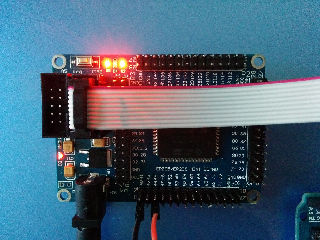
The development board is bare bones consisting only of the FPGA and circuitry for powering and programming it. As such, there is no direct way for the FPGA to communicate with my computer (which I wanted to use for sending and receiving serial data to and from the FPGA).
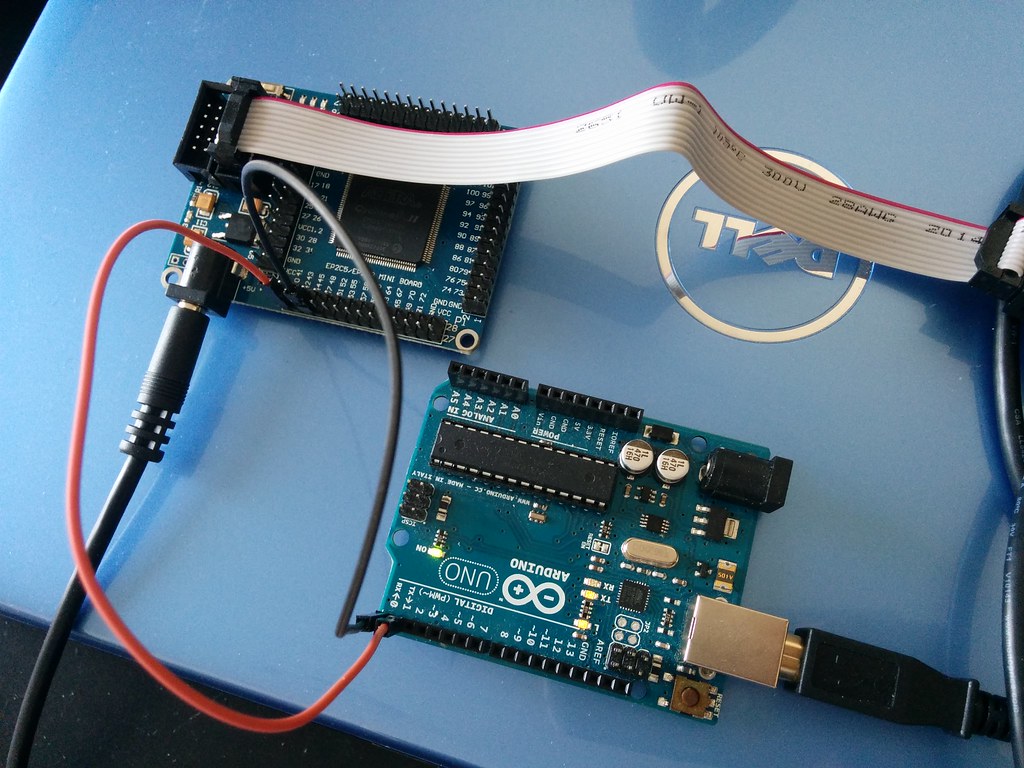
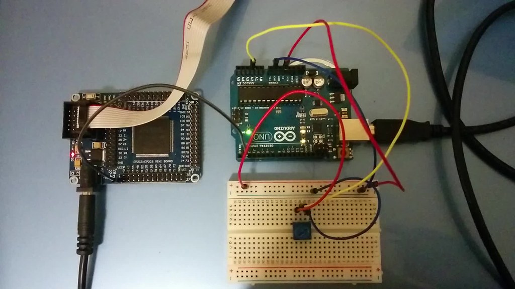
To get around this, I used an Arduino as the middle man. The Arduino already has USB and serial support. The USB end is used to send and receive data from the computer. And the serial end to send and receive data from another device using asynchronous serial communication. If you have access to one, you can use an FTDI adapter as the middleman instead.
This is what it looked like with everything connected. The FPGA uses two wires to send and receive serial data to and from the Arduino; and the Arduino uses USB to send and receive data to and from the computer. The white ribbon cable is not part of the circuit and is only used to program the FPGA.
Testing
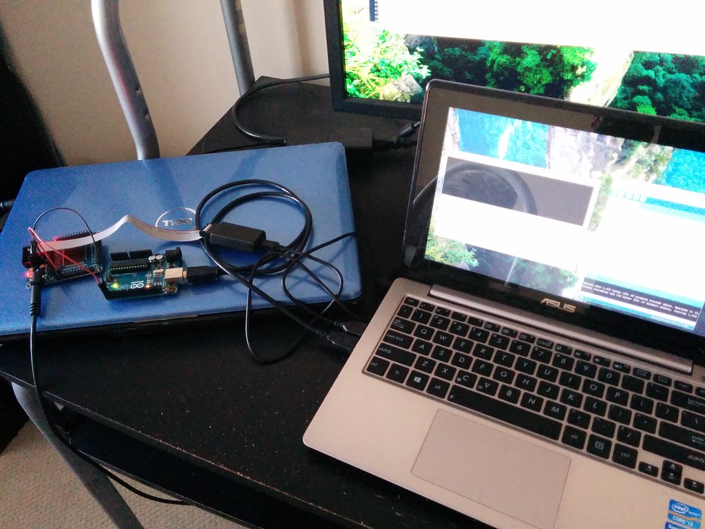
The Real Term software is used to display the data being sent between the FPGA and Arduino (for debugging).
To test whether the FPGA is working as intended, this is the relevant code:
if rising_Edge( CLK ) then

    -- Transmit if button pressed and transmitter not busy

    if BTN = '0' and active_TX = '0' then

        dataValid_TX <= '1';

        data_TX <= "01000001";  -- ASCII 'A'

    else

        dataValid_TX <= '0';

    end if;

    ---- Receive continously

    LEDS <= not data_RX( 2 downto 0 );  -- LEDs are active low

end if;
When the button on the development board is pressed, the FPGA transmits data. In this case it sends the byte 01000001. Similarly when the FPGA receives data, it turns on/off the three LEDs on the board accordingly. I’m using the LEDs to show the last three bits of the byte received. (Technically I could put eight LEDs on a breadboard and use them to show the full byte received, but I chose the path of least effort. Also with 60 plus IO pins on the FPGA, the only thing limiting how I display the byte received is my imagination.)
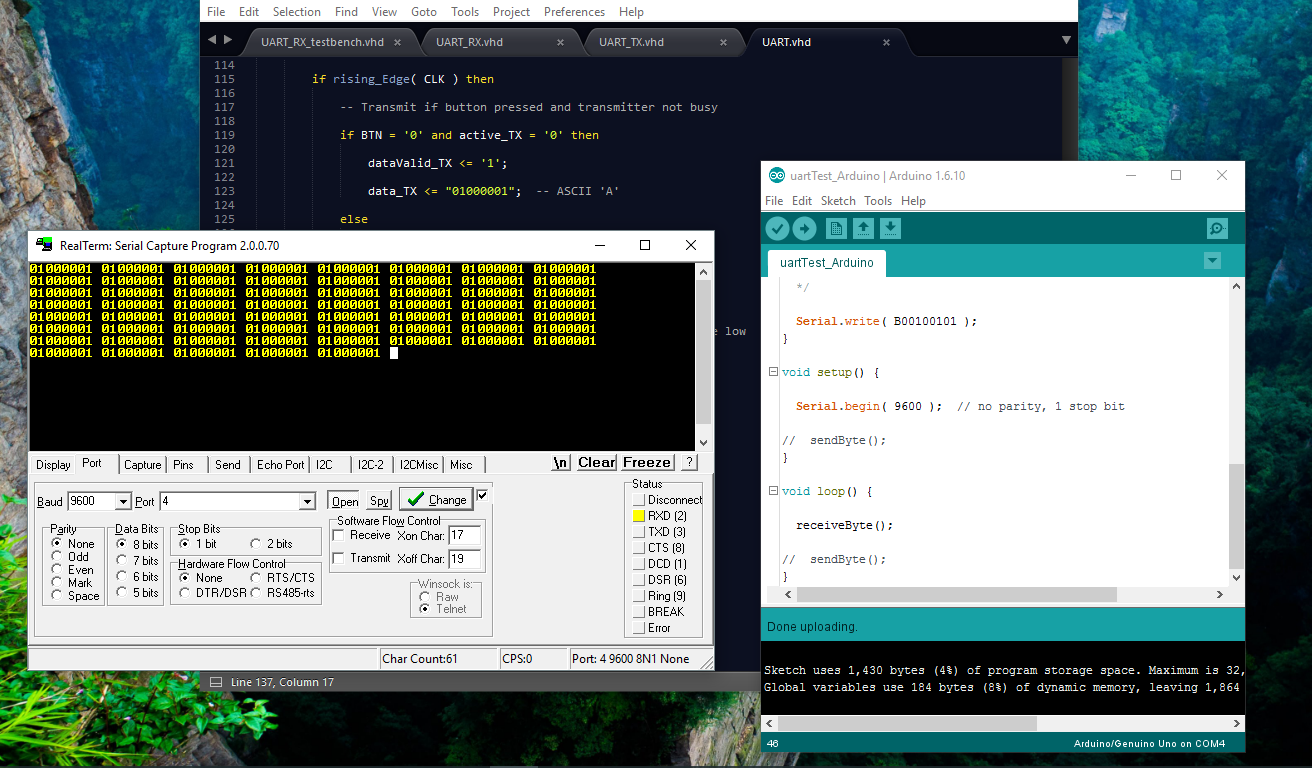
Debugging whether the FPGA successfully sends data is straightforward, just observe the data received via Real Term or via the Arduino IDE’s serial monitor. Here’s a screenshot:
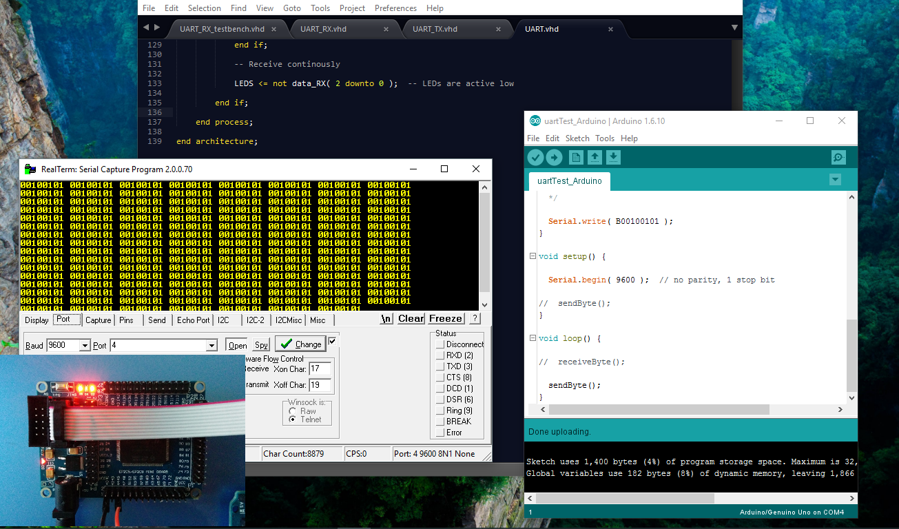
Similarly, to see if the FPGA is successfully receiving data, just observe the LEDs. Here’s a screenshot of it receiving 00100101:
It took a couple of tries, but I finally got something that works. It is definitely not the most robust code out there, but I understand how it works.
After I got it working, I thought it would be neat to use a potentiometer to change the data sent to the FPGA. So, I connected a potentiometer and modified the Arduino code to send its positional data. When the potentiometer is turned all the way to the left, the Arduino sends out a 0. When it is turned all the way to the right, the Arduino sends out a 7. And likewise a value in-between for all the positions in-between. The LEDs light up accordingly. Here’s a video of this in action:
One neat thing I learned from the Nandland tutorial is how to write testbench code to test the communication. Using software simulation to debug the code is far more precise and allows for faster iteration than using hardware (the whole thing with Arduino and Real Term). This will make implementing and testing the slightly more complex SPI and I2C protocols simpler.
Code