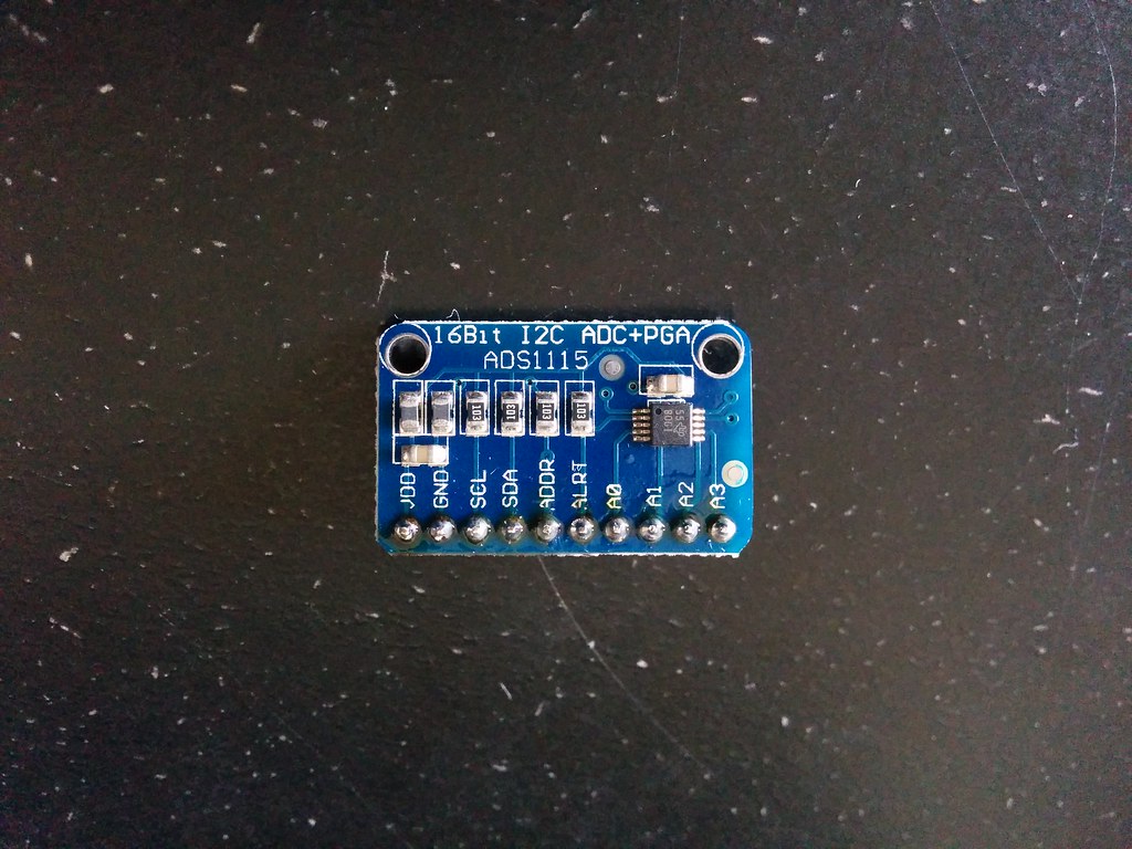
I bought an analog to digital converter for the computer.
The FPGA can only process digital signals (on or off, 3.3V or 0V) but the touch screen outputs analog signals (values ranging from 3.3V to 0V each representing a relative position).
It was my first time soldering (the header pins). As you can see, all the flux was used.
The ADC is an eBay knockoff of the ADS1115 offering from Adafruit. (Sorry Adafruit. I love your products and awesome work, but student budget at the moment. >< I promise to buy genuine in the future).
To communicate with the ADC, I followed this guide by Adafruit, and used their ADS1X15 library.
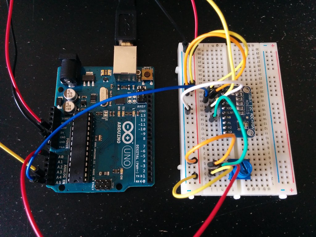
To test if the ADC was working as expected, I setup the simple photocell circuit shown in this tutorial by Adafruit. In the tutorial the circuit sends the analog reading from the photocell directly to an Arduino analog pin. The analog pin is connected to the Arduino’s internal ADC whose output you can read via the analogRead command.
int photocellPin = 0; // Arduino analog input pin which photocell output connected to
photocellReading_arduino = analogRead( photocellPin ); // 0 - 1023
To compare what the Arduino’s inbuilt ADC reads against what the ADS1115 chip reads, I tapped the analog output from the photocell and connected it to the analog input pin of the ADS1115. I then sent the ADS1115’s digital output to the Arduino.
int adc_analogInPin = 0; // ADS1115 analog input pin which photocell output connected to
photocellReading_ADS1115 = ads1115.readADC_SingleEnded( adc_analogInPin ); // 0 - ?
Then used the Arduino IDE’s serial monitor to view both readings.
Serial.print( photocellReading_ADS1115 );
Serial.print( " , " );
Serial.println( photocellReading_arduino );
Here is the complete code. Though the values were not identical in magnitude, their relative rate of change was similar implying that the ADS1115 was working. (The difference in magnitudes is likely because the Arduino’s built in ADC has a 10-bit precision whereas the ADS1115 has 16-bit).
For a more precise comparison, I used the same setup, but this time with a potentiometer in place of the photocell.
I got excited when I was reading the Adafruit tutorial and learned that the ADS1115 can be configured to generate an interrupt signal! Trying to continuously poll the touchscreen for change was a very imprecise endeavour that led to rather underwhelming results. However, if the ADC is capable of sending a signal whenever a specified condition is met, not only will detecting touches be more accurate, but it will also free up alot of the computer’s resources that would otherwise be tied up in polling.
So, I tweaked the code further to trigger an interrupt when the voltage read by the ADS1115 exceeds a threshold.
int interruptPin = 2; // Arduino input pin connected to 'Alert' output pin of ADS1115

void setup() {

  pinMode( interruptPin, INPUT );
  attachInterrupt( digitalPinToInterrupt( interruptPin ), handleInterrupt, FALLING );

  ads1115.startComparator_SingleEnded( adc_analogInPin, 16000 );
}

void loop() {

  potentiometerReading_ADS1115 = ads1115.getLastConversionResults();
  Serial.println( potentiometerReading_ADS1115 );
}

void handleInterrupt() {

  Serial.println( "teehee" );
}
Then tested it out, and it worked! Turning the potentiometer above the specified level led to the printing of “teehee”. Here is the complete code.
Upon reading the datasheet, I learned that it’s possible to not only trigger an alert when the input signal exceeds a specified threshold (“traditional mode”), but also when it falls within a specified range (“window mode”). The Adafruit library as is only supports the traditional mode. However, the Adafruit library is so well written, and so true to the datasheet that the only things I had to do to add support for the window mode were,
1) Copy the code of the traditional mode
2) Change the comparator mode register from ADS1015_REG_CONFIG_CMODE_TRAD to ADS1015_REG_CONFIG_CMODE_WINDOW
3) Then add a line that writes to the low threshold register
/**************************************************************************/
/*!
    JK -- added support
    @brief  Sets up the comparator to operate in window mode, causing the
            ALERT/RDY pin to assert (go from low to high) when the ADC
            value exceeds the specified high threshold or when the ADC
            value falls below the specified low threshold.

            This will also set the ADC in continuous conversion mode.
*/
/**************************************************************************/
void Adafruit_ADS1015::startComparatorWindow_SingleEnded(uint8_t channel, int16_t lo_threshold, int16_t hi_threshold)
{
  // Start with default values
  uint16_t config = ADS1015_REG_CONFIG_CQUE_1CONV   | // Comparator enabled and asserts on 1 match
                    ADS1015_REG_CONFIG_CLAT_LATCH   | // Latching mode
                    ADS1015_REG_CONFIG_CPOL_ACTVLOW | // Alert/Rdy active low   (default val)
                    ADS1015_REG_CONFIG_CMODE_WINDOW | // Window comparator
                    ADS1015_REG_CONFIG_DR_1600SPS   | // 1600 samples per second (default)
                    ADS1015_REG_CONFIG_MODE_CONTIN;   // Continuous conversion mode

  // Set PGA/voltage range
  config |= m_gain;

  // Set single-ended input channel
  switch (channel)
  {
    case (0):
      config |= ADS1015_REG_CONFIG_MUX_SINGLE_0;
      break;
    case (1):
      config |= ADS1015_REG_CONFIG_MUX_SINGLE_1;
      break;
    case (2):
      config |= ADS1015_REG_CONFIG_MUX_SINGLE_2;
      break;
    case (3):
      config |= ADS1015_REG_CONFIG_MUX_SINGLE_3;
      break;
  }

  // Set the high threshold register
  // Shift 12-bit results left 4 bits for the ADS1015
  writeRegister(m_i2cAddress, ADS1015_REG_POINTER_HITHRESH, hi_threshold << m_bitShift);

  // Set the low threshold register
  // Shift 12-bit results left 4 bits for the ADS1015
  writeRegister(m_i2cAddress, ADS1015_REG_POINTER_LOWTHRESH, lo_threshold << m_bitShift);

  // Write config register to the ADC
  writeRegister(m_i2cAddress, ADS1015_REG_POINTER_CONFIG, config);
}
I couldn’t believe how simple it was! Kudos to the team at Adafruit!
I changed the following line in the test program, and it worked as anticipated!
// ads1115.startComparator_SingleEnded( adc_analogInPin, 16000 );
int low_threshold = 10000;
int high_threshold = 16000;
ads1115.startComparatorWindow_SingleEnded( adc_analogInPin, low_threshold, high_threshold );
However for this alert feature to be useful with detecting touches, it needs to trigger when the input changes rather than when it falls within a specified range. I’m still trying to think of a clever way to do this.
In addition to translating Adafruit’s ADS1X15 Library into Hack’s high level language, it looks like I will have to implement I2C support in order to use this ADC with the computer.