Musings of a Fondue

Tag: Arduino

A VHDL Take on Ben Eater's CPU

IMG_20170903_132332

As part of the Homebrew Computer Project, I have been exploring other CPU architectures and their implementations in order to broaden my understanding of CPU design.

An awesome one that I came across was Ben Eater’s 8-bit computer. It is well documented through a series of videos on Youtube and also on his blog. The architecture is simple which allows you to get a firm understanding of all its components.

Since it is a known working design, I saw it as the perfect opportunity to practice implementing a CPU in VHDL.
LCD Woes - Back With a Vengeance

After months of waiting the new LCD assembly finally arrived!

I noticed the PCB had a different layout than the one I had earlier. Gone was the onboard voltage regulator. Yay cost cutting! Also missing was the ZIF connector. In this one, the LCD flex cable was soldered directly onto the PCB, yay more cost cutting! Given the trouble I had earlier trying to resolder the four chunky traces of the touch screen cable, prospects looked dim for resoldering the many small traces of the LCD screen cable. Drilling mounting holes onto the PCB no longer looked like an option.

Before doing anything, I checked whether the LCD works. I connected it to an Arduino and loaded Adafruit’s graphics test. It sort of worked. But not quite. The screen flickered and what rendered looked glitchy. See the video* below for what I mean. Contrast this with what the test is supposed to look like.

Not quite right

RAM for the Computer

IMG_20170130_162235

Internal RAM

My original plan was to use the FPGA for RAM, either by building the RAM in VHDL using flip flops or by using the FPGA’s dedicated RAM blocks.

An ADC for the Computer

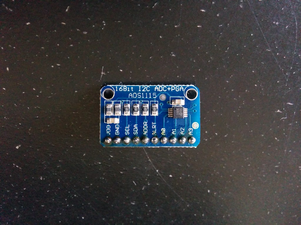
I bought an analog to digital converter for the computer.

IMG_20160831_154310

The FPGA can only process digital signals (on or off, 3.3V or 0V) but the touch screen outputs analog signals (values ranging from 3.3V to 0V each representing a relative position).

It was my first time soldering (the header pins). As you can see, all the flux was used.

A Keyboard for the Computer

Much like Charles’s hardware setup (see a pattern here?), I decided to use part of the touch screen as the keyboard for the computer.

Design

I roughed out the design using Inkscape. (Because unlike Photoshop or Gimp, you can easily move and resize shapes around after creating them).

I then recreated the design using JavaScript. I used Khan Academy’s coding environment* to do this because its live update feature made iteration and tweaking a breeze. Converting the Inkscape design to code using the Arduino IDE would have been a tedious process as I would have had to upload the sketch each time I wanted to see the effect of a change made.

In the JavaScript code, I used only basic functions that are supported by the Adafruit Graphics Library such as drawRect, drawText, and fillColor. The color scheme is based on this palette with tweaks here and there.

Below is the Javascript mockup. Try typing. Clicking the up arrow toggles the keyboard’s style.

Non-volatile Memory for the Computer

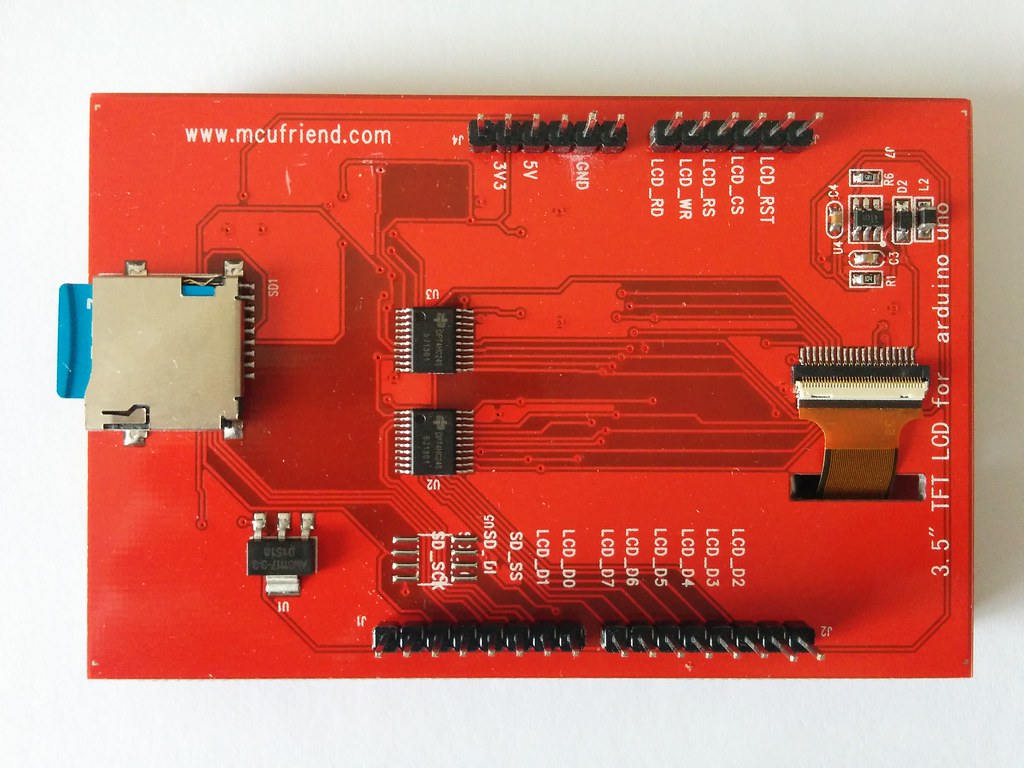
I’m looking at the SD card reader attached to the Mcufriend LCD shield… and thinking it can act as the non-volatile memory for the Hack computer.

When used with the Arduino SD Library, one can easily read, write, create, and remove files (and directories).

The SD card solution is also very convenient! You can plug the SD card into any regular computer (or phone) and copy onto it any programs you want to run on the Hack Computer (for example these games on Github). (Think game cartridge or USB thumb drive). Similarly, if you write a program and save it onto the SD card when using the Hack Computer, you can then open it up later on any other computer (or phone).

A Screen for the Computer

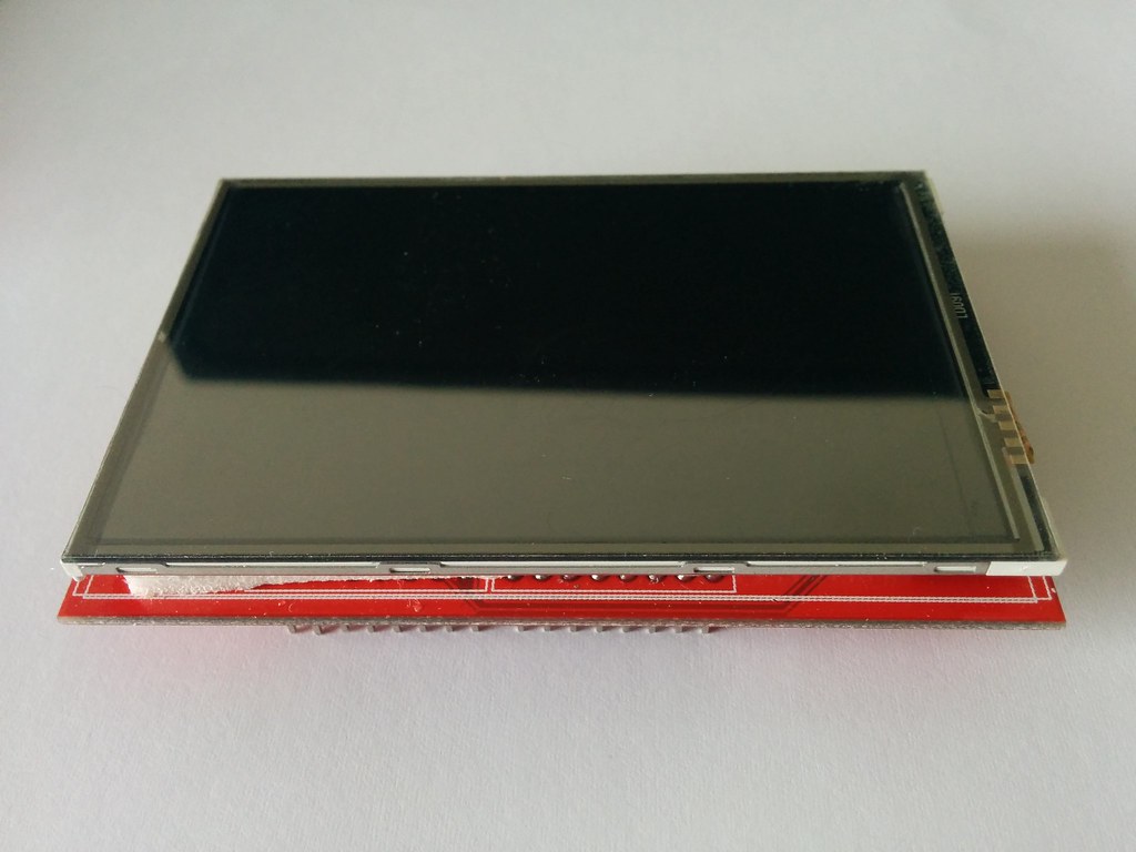
I bought this Mcufriend touch screen. It’s the unbranded version of this one sold by Adafruit.

Front

Back

I got it for $10 compared to Adafruit’s price of $40. I came across the screen through this awesome video by Charles Cole where he walks through his FPGA implementation of a Z-Machine. I also bought the Altera mini dev board he recommends ($20 which is a steal) but that’s another post.

My gameplan is

  • To first get it working on Arduino (since there is information available online on how to do so).
  • Once it works on Arduino, convert the relevant files (driver, graphics) from C, Python, or whichever language is used to Hack Computer’s high level language.
  • Then change a few things here and there on the Hack Computer so that it outputs for the LCD screen instead of Tkinter.

Part 1) Getting the screen to work

Flashing a BIOS With Arduino

This was a double team with my brother.

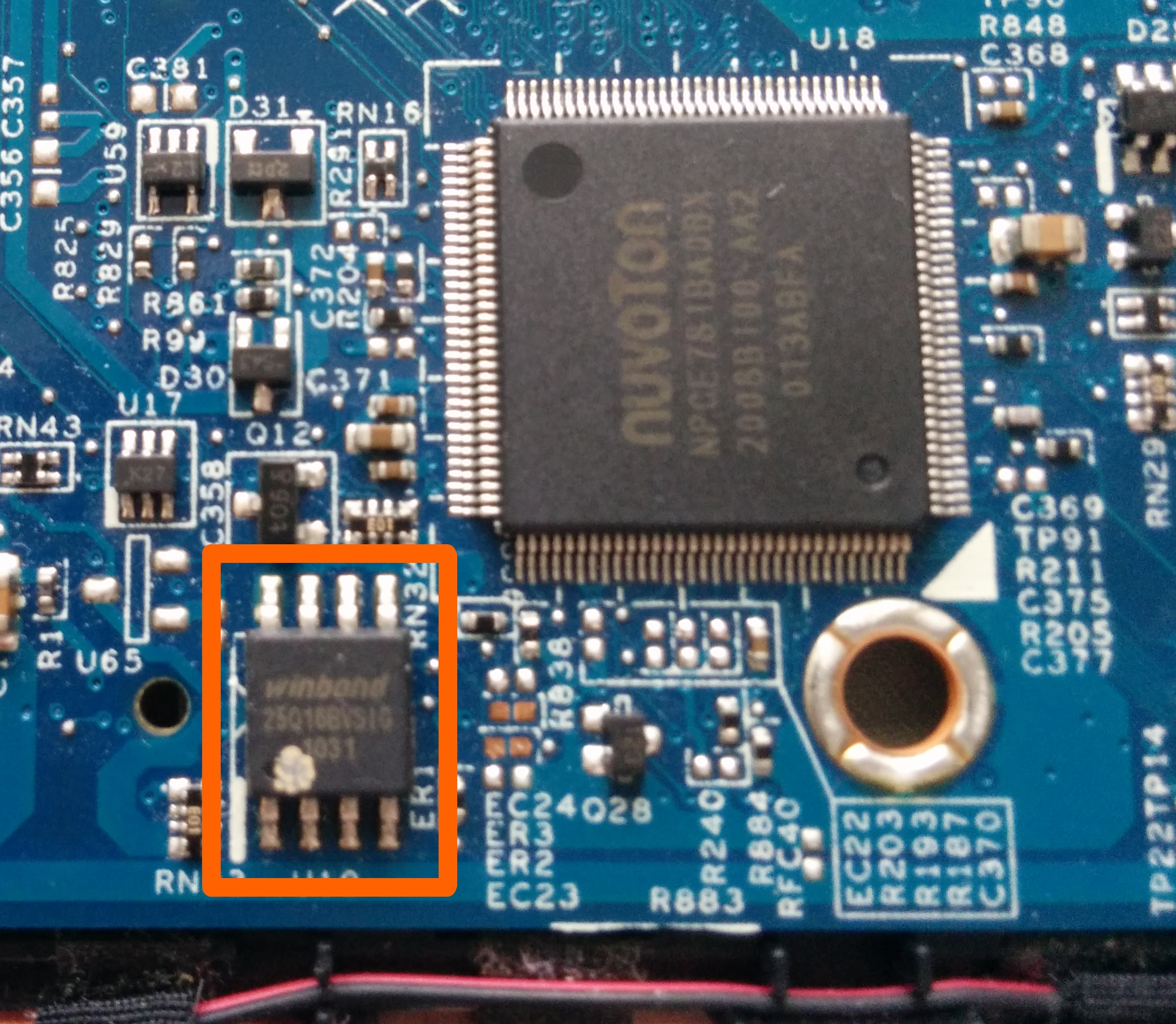
We had a laptop that did not boot and was outside its warranty. After exhaustively checking possible fail points, we narrowed down the likely culprit to a BIOS failure.

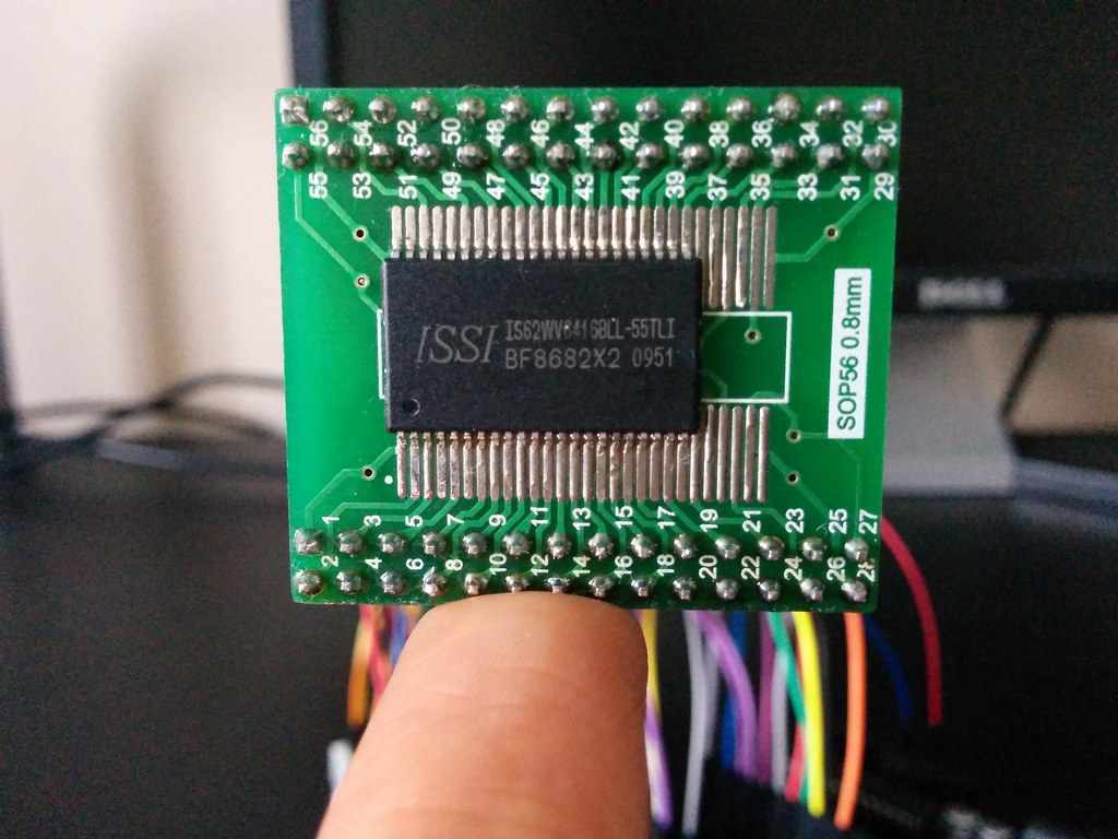
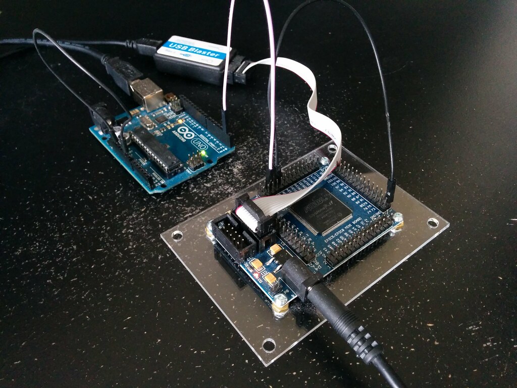
Inspired by this Hackaday post, we decided to use an Arduino to flash the chip. The laptop was going to be scrapped otherwise, so we figured we might as well go all out.

image of BIOS chip

A Simple Arduino Game

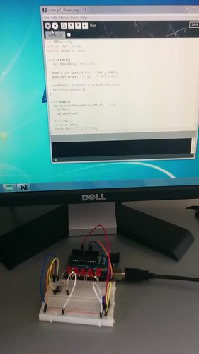
I made a game.

It’s a combination of two tutorials. The game mechanics are based on the LED Game tutorial by PyroElectro. The use of Processing to show the score and time is based on Jeremy Blum’s tutorial.

Gameplay,

  • Press button when middle LED is on
  • Points get per hit depend on how fast the wave is going (1 to maximum of 7)
  • Speed of the wave increases as time elapses. It is also adjustable at any time with the potentiometer
  • At 30 seconds remaining, player gets alerted (LEDs blink and Processing display starts pulsing)

Arduino game