I chose to use VHDL to program the FPGA because it is closer to a schematic representation than Verilog. Verilog seems (to me) like learning a new programming language whereas VHDL is more like describing the circuit.
For example, take the construction of a full adder. Here is a video of the structure generated by my code below:
And the code:
------- Full Adder ------------


entity fullAdder_v is

    port(
        a, b, cIn : in std_logic;
        sum, cOut : out std_logic
    );

end entity;


architecture ac of fullAdder_v is

    signal sum1, carry1, carry2 : std_logic;

begin

    comp0 : halfAdder_v port map(    a,   b, sum1, carry1 );
    comp1 : halfAdder_v port map( sum1, cIn,  sum, carry2 );
    comp2 : or_v port map( carry1, carry2, cOut );

end architecture;


------- Half Adder ------------


entity halfAdder_v is

    port(
              a, b : in std_logic;
        sum, carry : out std_logic
    );

end entity;


architecture ac of halfAdder_v is
begin

    comp0 : xor_v port map( a, b, sum );
    comp1 : and_v port map( a, b, carry );

end architecture;


------- and -------------


entity and_v is

    port(
        a, b : in std_logic;
           q : out std_logic
    );

end entity;


architecture ac of and_v is
begin

    q <= a and b;

end architecture;


------- xor -------------


entity xor_v is

    port(
        a, b : in std_logic;
           q : out std_logic
    );

end entity;


architecture ac of xor_v is
begin

    q <= a xor b;

end architecture;


------- or -------------


entity or_v is

    port(
        a, b : in std_logic;
           q : out std_logic
    );

end entity;


architecture ac of or_v is
begin

    q <= a or b;

end architecture;
Breaking it down, this part of the code says that the fullAdder ‘box’ has signals a, b, and cIn coming in as inputs. It also has signals sum and cOut coming out as outputs.
entity fullAdder_v is

    port(
        a, b, cIn : in std_logic;
        sum, cOut : out std_logic
    );

end entity;
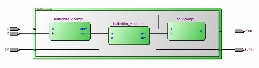
And this part of the code describes what the inside of the fullAdder ‘box’ looks like. The signals sum1, carry1, and carry2 are the wires connecting stuff inside the box. Input signals a and b go into a halfAdder ‘box’. The outputs of this halfAdder box are sum1 and carry1. One of these outputs, sum1, along with the cIn input go into another halfAdder box which outputs sum and carry2. The carry1 and carry2 outputs go into an or box which outputs cOut. See the diagram above.
architecture ac of fullAdder_v is

    signal sum1, carry1, carry2 : std_logic;

begin

    comp0 : halfAdder_v port map(    a,   b, sum1, carry1 );
    comp1 : halfAdder_v port map( sum1, cIn,  sum, carry2 );
    comp2 : or_v port map( carry1, carry2, cOut );

end architecture;
The same structure (entity and architecture) is repeated for all the ‘boxes.’
In this way, you describe the schematic for all the components that makeup the Hack Computer. You also end up with a blueprint which when implemented physically (for example with Legos, transistors, relays, dominoes, or redstone) results in a functionally identical computer. (The FPGA implementation is just easier to prototype and iterate as all you have to do is flash the new configuration onto the chip versus physically reconfiguring components).
I am using a structural approach in the VHDL code whereby you describe everything (what connects to what, and what everything looks like inside) and leave nothing up to the synthesis software to create on your behalf (as is done in Behavioral and RTL style programming). For more on the differences see this link.
So far the VHDL code looks very much like the code used in the Python simulation of the computer. I am also creating similar test files for each component in VHDL. The tests use a behavioural approach as they are not part of the computer architecture. For example, here is the test code for the full adder above.
Tutorials
I got up to speed on VHDL largely due to Jim Pytel’s awesome tutorials on Youtube. I’ve included the relevant videos in this playlist (his videos are part of a larger course so not all of them are directly related to VHDL). The playlist also has other VHDL tidbits I’ve found of interest to someone starting out, and I’ll keep adding to it accordingly.
For getting familiar with Altera’s Quartus software (used to flash the FPGA I have) I turned to Pyro Electro’s Youtube series.
Another invaluable resource is this VHDL Reference Guide.