Remember how I bought the screen/digitizer/frame assembly so I wouldn’t have to deal with glue. Well,
Remember how I bought the screen/digitizer/frame assembly so I wouldn’t have to deal with glue. Well,
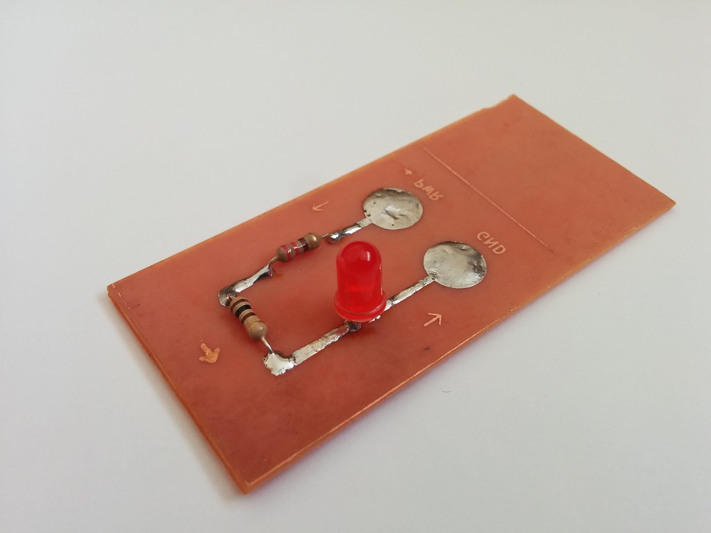
Just a simple “led and resistor” circuit to test the end-to-end process of making a circuit board.
Unfortunately, I forgot to flip the image before printing, and only noticed after the board was already etched.

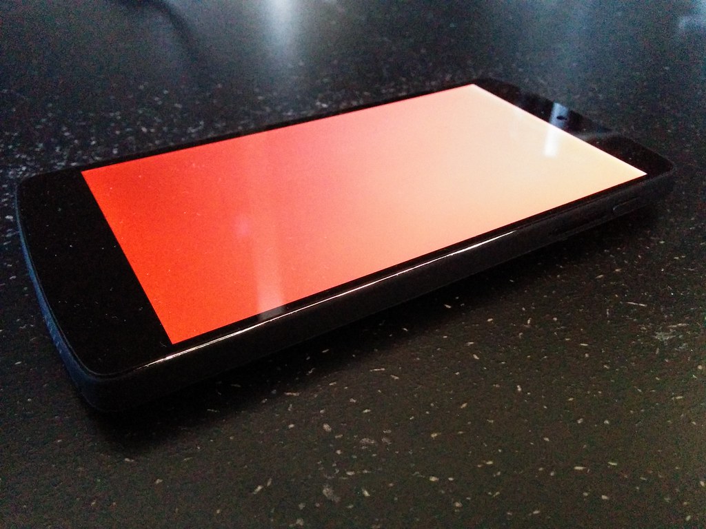
After what feels like years, the screen finally arrived!
I ordered the screen and frame assembly. Though it costs more and you loose the OEM frame, installation is much easier. Rather than trying to peel off the cracked screen and glue in a new one, you can “just” swap components from the old frame to the new one.
The quality of the assembly is great for a replacement and the price I paid. The flex cable looked a bit worn… maybe the screen was a salvage? The frame is of a lower quality than the OEM frame, but this is to be expected.
Tools useful for this repair:
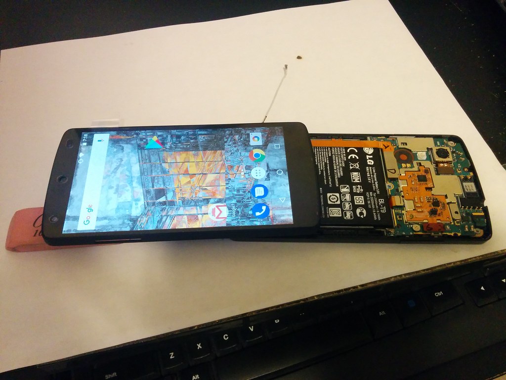
In the image below, I am testing that the screen works before moving components from the old frame to the new one:
I dropped my phone one too many times. This time the screen gave in and shattered.1 Whether related or not, my power button soon failed after and my phone was unable to boot. It would get about a second into the boot process before restarting again, as if the power button was constantly being pressed. The behaviour was the same even in recovery mode indicating that it was likely a hardware rather than software problem.
A Google search revealed that failure of the power button is a common problem with the Nexus 5. I tried the easy solution of partially disassembling the phone to get at the button and clean it, its rubber pad, and the surrounding area with isopropyl alcohol. Unsurprisingly, it didn’t work.
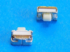
In my search, I came across this awesome article by Gregor van Egdom. It has a great explanation and photos of how this particular button works and why it likely fails. His solution is to replace the button. So I went ahead and ordered a replacement from Ebay ($5 with shipping from the US (I could have gotten it cheaper but I wanted it now rather than later as my phone was unusable)).
Below are instructions on how to simulate the VHDL implementation of Ben Eater’s computer. They also double as a general introduction to ModelSim.
Running the simulation
1) Get ModelSim. It’s free software.
2) Download the VHDL code from Github.
3) Open ModelSim, and create a new project.
As part of the Homebrew Computer Project, I have been exploring other CPU architectures and their implementations in order to broaden my understanding of CPU design.
An awesome one that I came across was Ben Eater’s 8-bit computer. It is well documented through a series of videos on Youtube and also on his blog. The architecture is simple which allows you to get a firm understanding of all its components.
Since it is a known working design, I saw it as the perfect opportunity to practice implementing a CPU in VHDL.
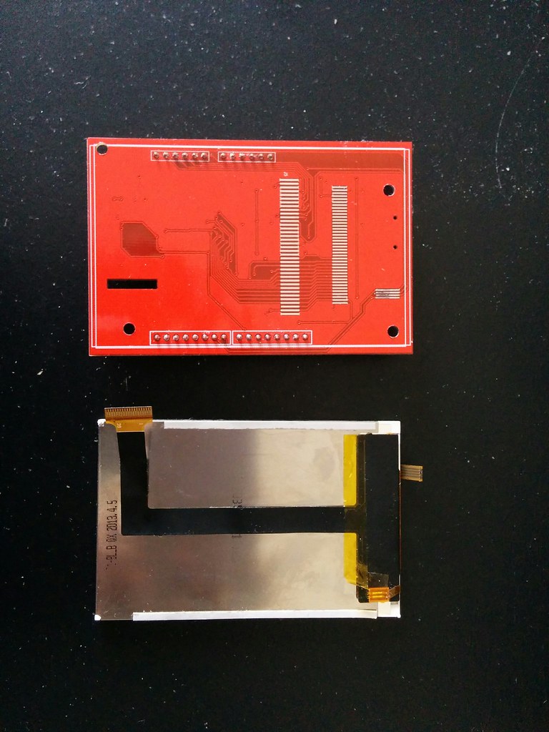
After months of waiting the new LCD assembly finally arrived!
I noticed the PCB had a different layout than the one I had earlier. Gone was the onboard voltage regulator. Yay cost cutting! Also missing was the ZIF connector. In this one, the LCD flex cable was soldered directly onto the PCB, yay more cost cutting! Given the trouble I had earlier trying to resolder the four chunky traces of the touch screen cable, prospects looked dim for resoldering the many small traces of the LCD screen cable. Drilling mounting holes onto the PCB no longer looked like an option.
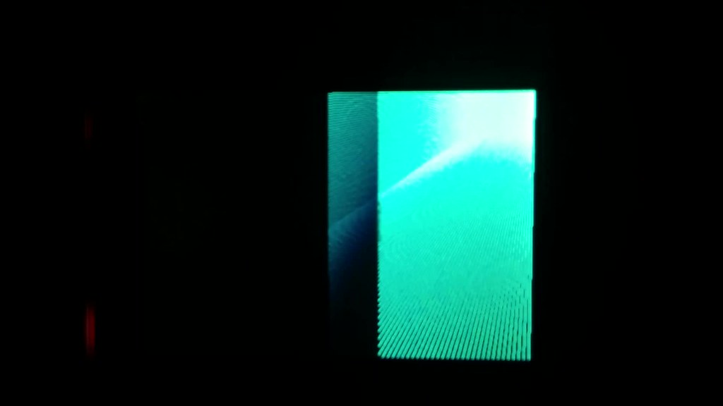
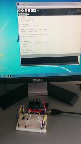
Before doing anything, I checked whether the LCD works. I connected it to an Arduino and loaded Adafruit’s graphics test. It sort of worked. But not quite. The screen flickered and what rendered looked glitchy. See the video* below for what I mean. Contrast this with what the test is supposed to look like.
It was time to put the previously disassembled LCD assembly back together. Reconnecting the LCD to the PCB was easy enough (given that it was a ZIF connector). However reconnecting the touch screen would prove to be my undoing.
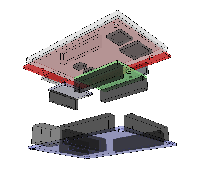
I had a hard time figuring out how to mount the LCD assembly. It was designed for use as an Arduino shield and thus its PCB had no mounting holes. I wanted a solution that was sturdy but non-permanent so things like glue were not options. I came across these clips from Adafruit, but they didn’t seem rugged enough to support the handling the touch screen (and hopefully handheld computer) was going to receive.
Internal RAM
My original plan was to use the FPGA for RAM, either by building the RAM in VHDL using flip flops or by using the FPGA’s dedicated RAM blocks.
Next in line in the awesome tutorial series from Nandland was VGA. I didn’t have a VGA connector for my FPGA, but wondered if I could jury-rig something with what I had on hand.
The wiring diagram below from Grant Seale’s Multicomp gave me a very good idea on how to go about it.
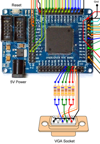
In the Nandland tutorial (image below), three signals are used per channel instead of two so my setup reflects that.
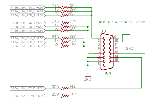
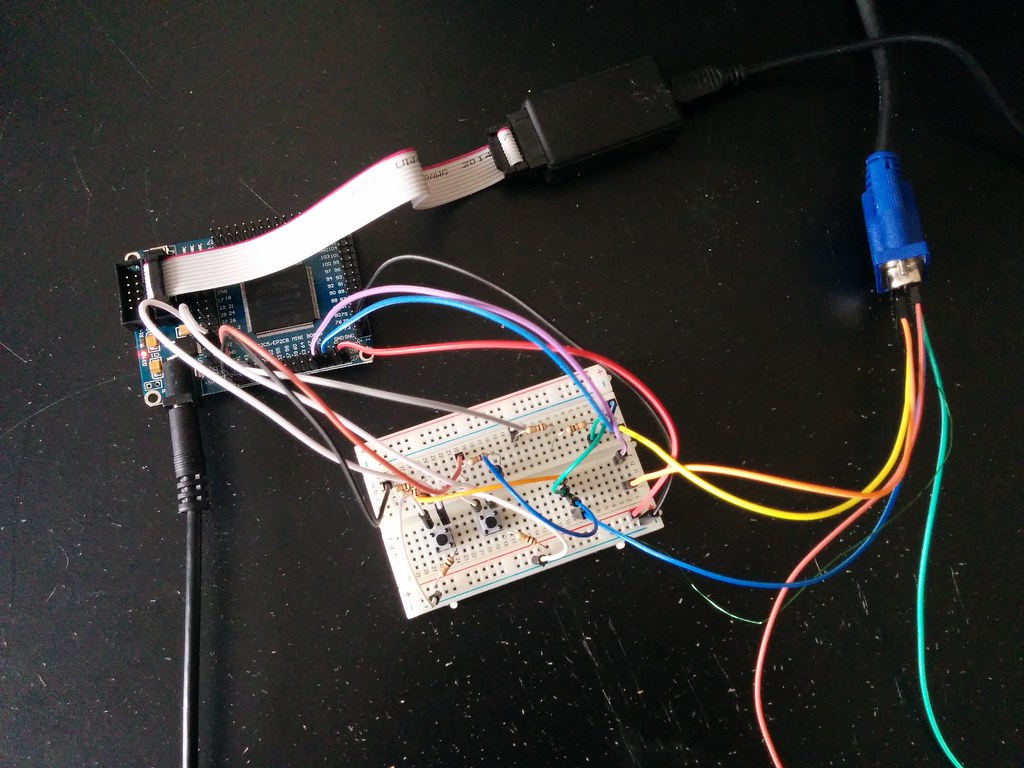
I had five 1Kohm resistors on hand, enough to control one channel. I used two of them in parallel to get the 500 ohms (close enough to 549), two in series to get the 2K ohms, and one on its own for the 1K ohms. Jumper wires were used to connect to the pins (red, green, blue, hsync, vsync). Luckily, all the ground pins were in-line (and the random pin in-between was an unused pin) so I just tied the whole line to ground using one wire (instead of several jumper wires). Here is the final masterpiece:
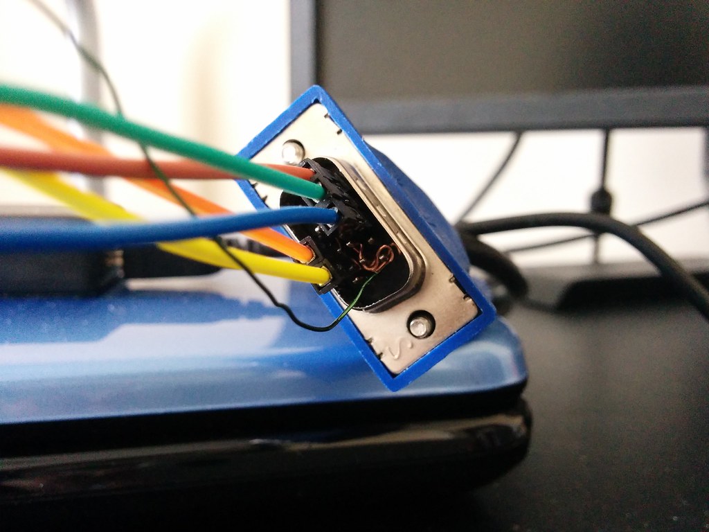
And the overall setup:
For the homebrew computer, I will need to implement SPI and I2C support to allow the FPGA to communicate with the LCD screen and ADC. To get an idea of how to go about this, I turned to tutorials uploaded on Youtube. But before getting in deep, I started by learning a simpler protocol, asynchronous serial communication.
I chose to use VHDL to program the FPGA because it is closer to a schematic representation than Verilog. Verilog seems (to me) like learning a new programming language whereas VHDL is more like describing the circuit.
For example, take the construction of a full adder. Here is a video of the structure generated by my code below:
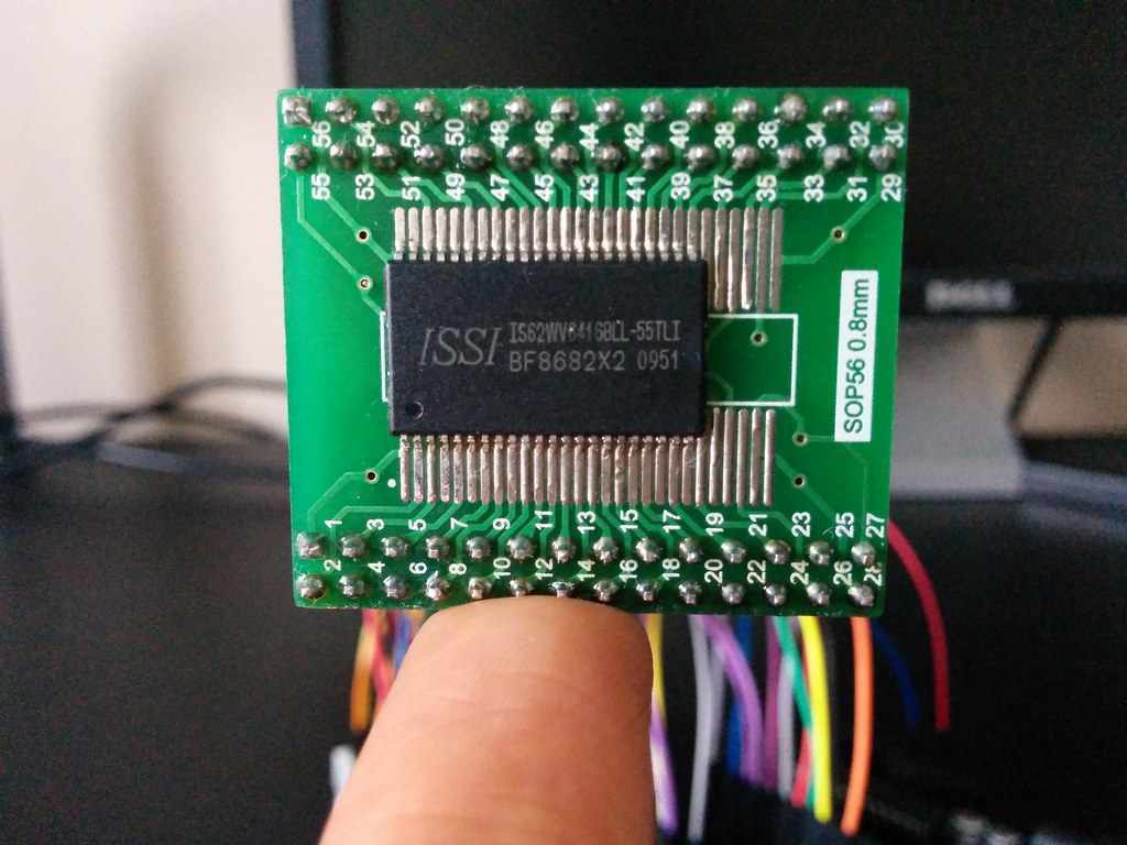
I bought an analog to digital converter for the computer.
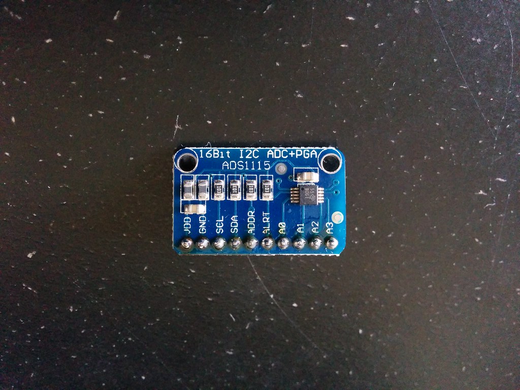
The FPGA can only process digital signals (on or off, 3.3V or 0V) but the touch screen outputs analog signals (values ranging from 3.3V to 0V each representing a relative position).
It was my first time soldering (the header pins). As you can see, all the flux was used.
Much like Charles’s hardware setup (see a pattern here?), I decided to use part of the touch screen as the keyboard for the computer.
Design
I roughed out the design using Inkscape. (Because unlike Photoshop or Gimp, you can easily move and resize shapes around after creating them).
I then recreated the design using JavaScript. I used Khan Academy’s coding environment* to do this because its live update feature made iteration and tweaking a breeze. Converting the Inkscape design to code using the Arduino IDE would have been a tedious process as I would have had to upload the sketch each time I wanted to see the effect of a change made.
In the JavaScript code, I used only basic functions that are supported by the Adafruit Graphics Library such as drawRect, drawText, and fillColor. The color scheme is based on this palette with tweaks here and there.
Below is the Javascript mockup. Try typing. Clicking the up arrow toggles the keyboard’s style.
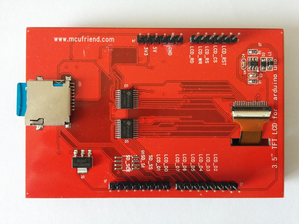
I’m looking at the SD card reader attached to the Mcufriend LCD shield… and thinking it can act as the non-volatile memory for the Hack computer.
When used with the Arduino SD Library, one can easily read, write, create, and remove files (and directories).
The SD card solution is also very convenient! You can plug the SD card into any regular computer (or phone) and copy onto it any programs you want to run on the Hack Computer (for example these games on Github). (Think game cartridge or USB thumb drive). Similarly, if you write a program and save it onto the SD card when using the Hack Computer, you can then open it up later on any other computer (or phone).
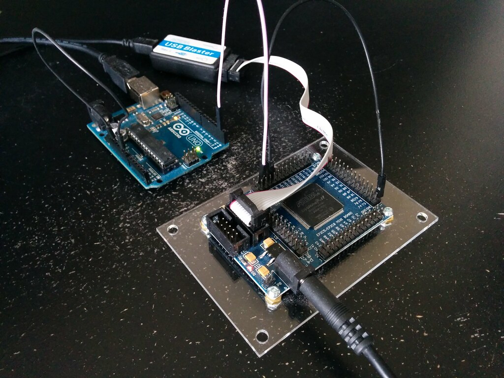
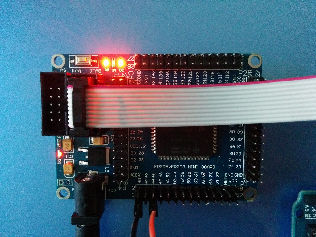
I’ll be using the Altera Cyclone II - Mini Development Board as the main FPGA of the Hack Computer V1 (name pending).
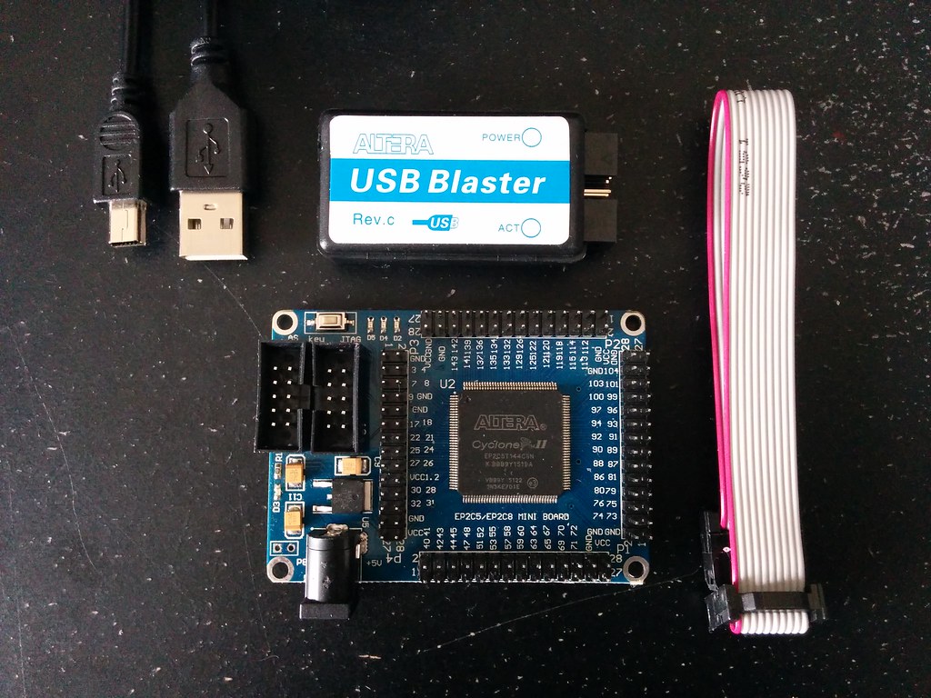
I got it for $20 on eBay and the kit came with a (knockoff) USB Blaster for programming. The idea to use the board came from Charles Cole’s hardware setup of his homebrew Z-Machine. The price is great and I love that it only has the bare minimum components on it.
I worked through this excellent getting started guide by Trey Dahlberg on Youtube and everything seems to be running well.
Specs:
Update (January 18, 2017):
I recently came across the Multicomp project by Grant Searle. In it he uses this development board and consequentially has a ton of really helpful information on the board and some of the things it’s capable of. The project is described by Hackaday as a ‘pick and mix retrocomputer’ which allows you to use the FPGA as a Z80, 6502, 6800 or whatever CPU mashup you feel inspired to. His project also describes in detail interfacing with various devices including SRAM, SD cards, VGA, composite video, PS/2, USB - basically I found the holy grail! Check out the project page to learn more about the board, and maybe even build a mix and match computer of your own.
Note: if you use this development board, make sure to desolder the four zero ohm resistors as explained in Grant’s project page.
I bought this Mcufriend touch screen. It’s the unbranded version of this one sold by Adafruit.
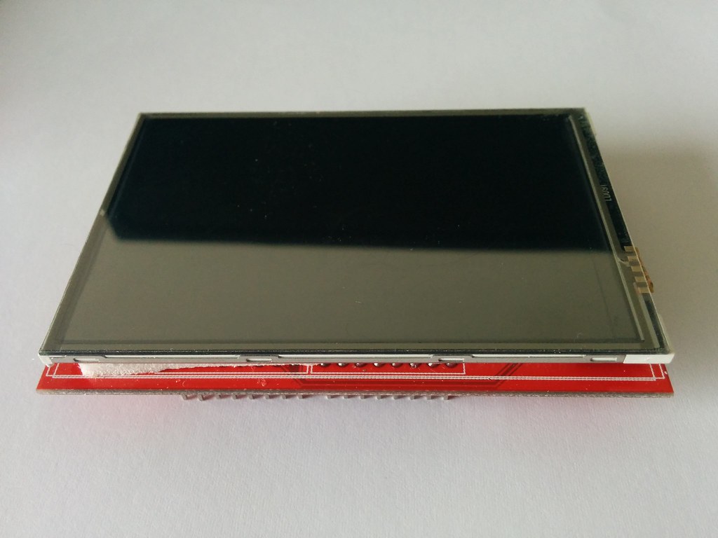
I got it for $10 compared to Adafruit’s price of $40. I came across the screen through this awesome video by Charles Cole where he walks through his FPGA implementation of a Z-Machine. I also bought the Altera mini dev board he recommends ($20 which is a steal) but that’s another post.
My gameplan is
Part 1) Getting the screen to work
I finished the first half of the course. 
And here’s a video of what my implementation looks like in action.
It can run programs! Albeit very slowly. The demo above is vastly sped up. In realtime, it took about 37 minutes to run.
The code for the emulator is on Github.
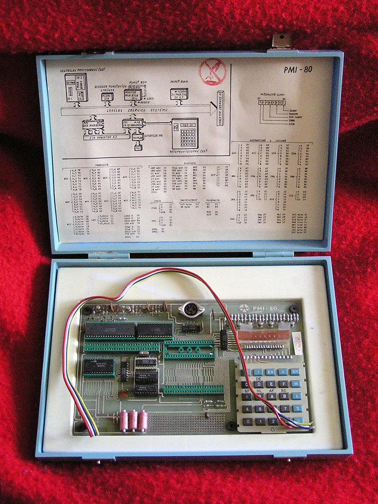
Goal - to build a homebrew computer. From scratch.
Inspiration comes from these single board briefcase computers photographed by Rostislav Lisovy.
I made a game.
It’s a combination of two tutorials. The game mechanics are based on the LED Game tutorial by PyroElectro. The use of Processing to show the score and time is based on Jeremy Blum’s tutorial.
Gameplay,
An oldie but goodie Hello World tutorial for the Arduino,
Here are some videos from working through it,
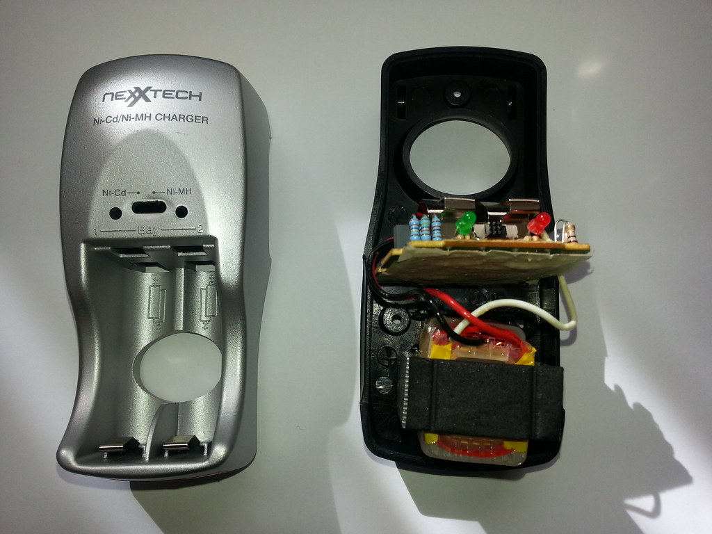
The following sites have exposed me to a whole world I had no idea existed. And it’s mind blowing!
Eager to learn their language, and since this battery charger was the closest thing on hand I could open up, it will be my guinea pig. My goal with the charger is to be able to identify all the components on it, how they work together to accomplish their intended task, draw a schematic for it, and recreate its PCB. I figure in the process I’ll learn a lot about Hardware and Electronics.