I had a hard time figuring out how to mount the LCD assembly. It was designed for use as an Arduino shield and thus its PCB had no mounting holes. I wanted a solution that was sturdy but non-permanent so things like glue were not options. I came across these clips from Adafruit, but they didn’t seem rugged enough to support the handling the touch screen (and hopefully handheld computer) was going to receive.
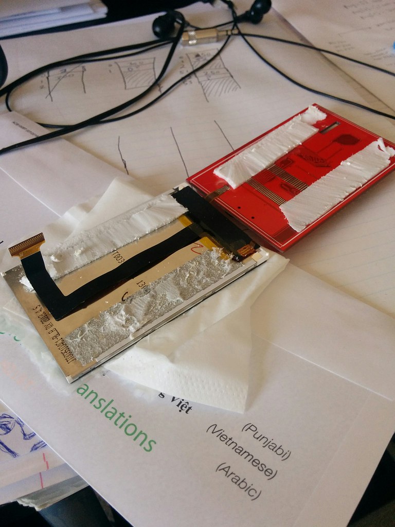
One day out of frustration I decided to take apart the LCD assembly and see if I could just drill the holes needed.
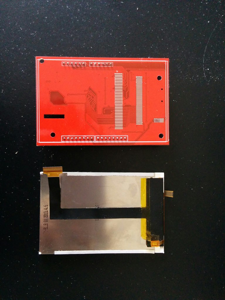
Disassembly was luckily not too complicated. All that was required was to disconnect the ZIF connecting the LCD to the PCB, remove the tape securing the LCD onto the PCB, and to desolder the flex cable connecting the touch screen to the PCB.
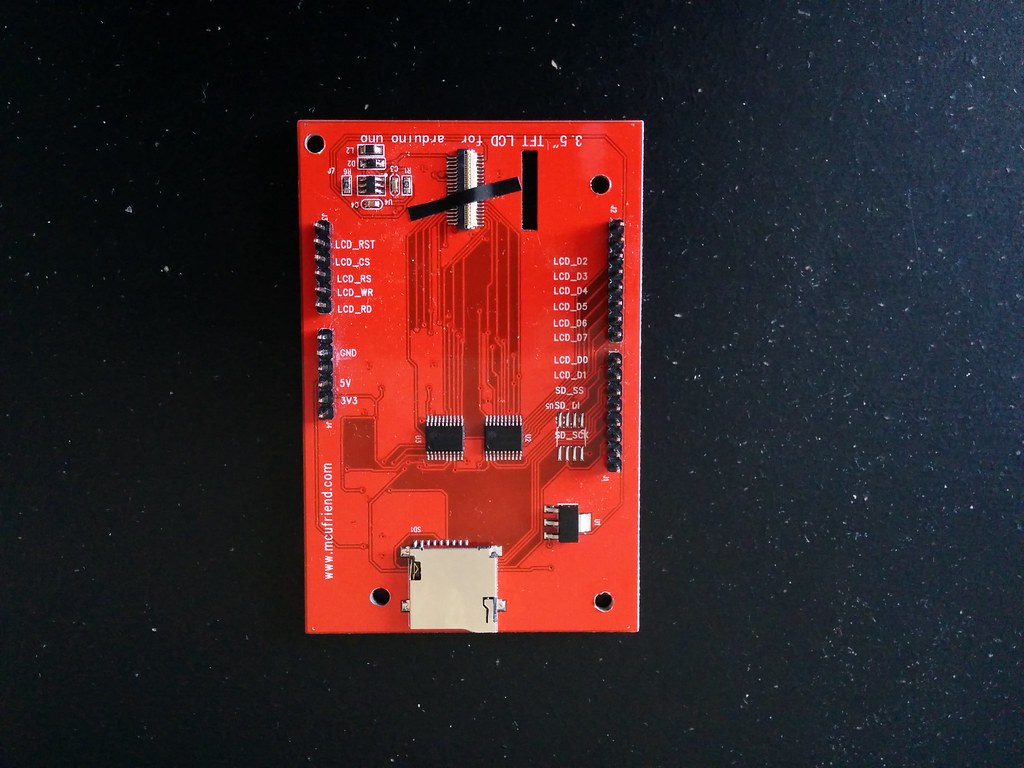
Looking at the PCB it was apparent that it was just a two layer board (traces on the top and bottom). This meant that drilling would not cut any hidden traces. I marked out some spots near the corners where there were no visible traces on either side, then proceeded to drill the holes. Surprisingly, a standard hand drill with standard drill bits did the job. Here is the end result:
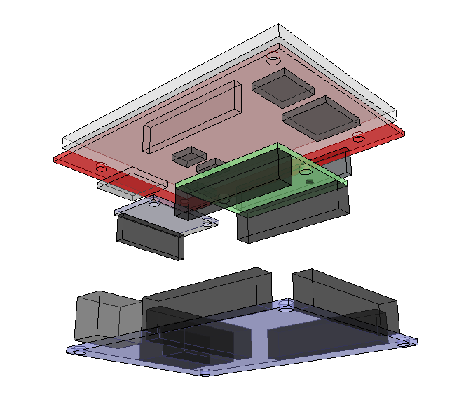
With the issue of mounting the LCD assembly sorted out, I moved on to designing a case for the computer. For this I used Sketchup and Inkscape.

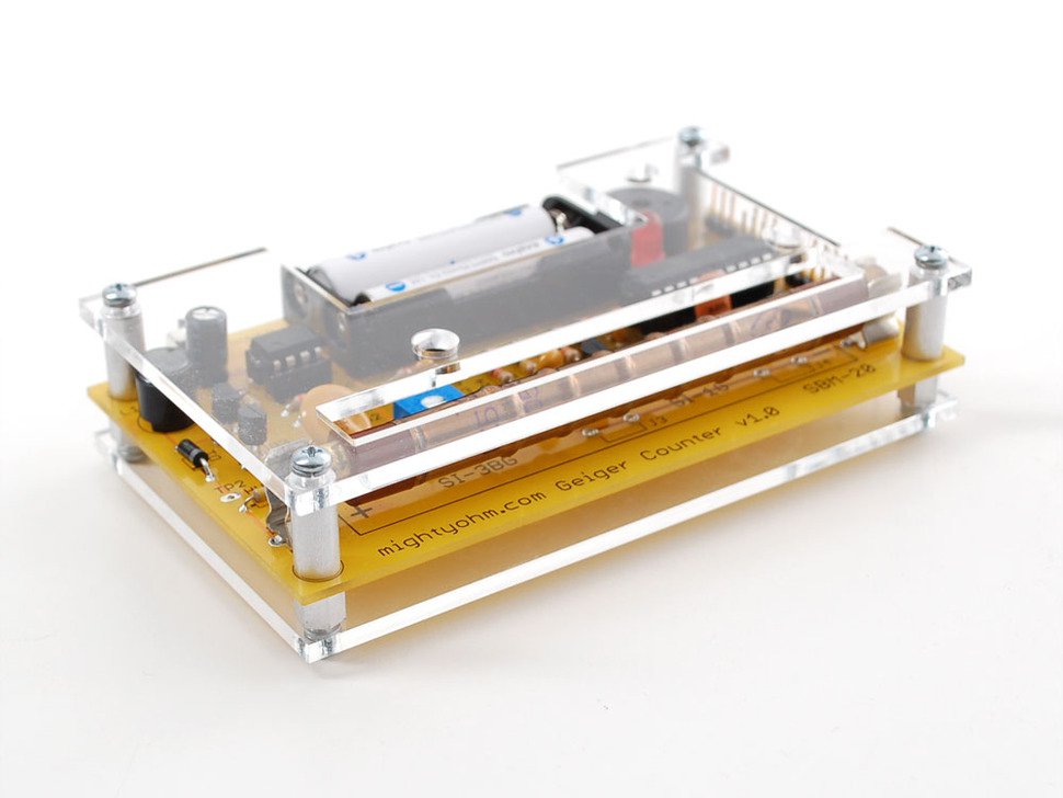
I was aiming for the simple laser cut clear acrylic style that the Mighty Ohm Geiger Counter uses.
Since none of the PCBs had measurements available from the seller, I measured them using a ruler. I tested the fit by printing out the design on paper and cutting using good old scissors. Several iterations and tweaks later I got the fit right.
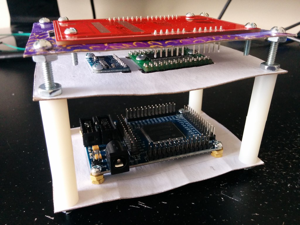
I bought an acrylic sheet from a hardware store and headed to our local Hackerspce to get it laser cut. There I got awesome help converting the SVG into something the laser cutter could understand and cutting the piece. Here’s a picture* of the end result:

With the case done, it was now simply a matter of putting the LCD assembly together and connecting all the components. Or so I thought…
*The picture is a recent one. I intended to take a beauty shot after final assembly, but for reasons that will become apparent in the next post this never happened.