After months of waiting the new LCD assembly finally arrived!
I noticed the PCB had a different layout than the one I had earlier. Gone was the onboard voltage regulator. Yay cost cutting! Also missing was the ZIF connector. In this one, the LCD flex cable was soldered directly onto the PCB, yay more cost cutting! Given the trouble I had earlier trying to resolder the four chunky traces of the touch screen cable, prospects looked dim for resoldering the many small traces of the LCD screen cable. Drilling mounting holes onto the PCB no longer looked like an option.
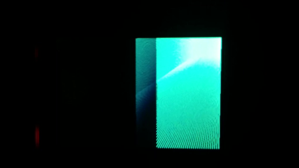
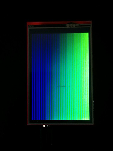
Before doing anything, I checked whether the LCD works. I connected it to an Arduino and loaded Adafruit’s graphics test. It sort of worked. But not quite. The screen flickered and what rendered looked glitchy. See the video* below for what I mean. Contrast this with what the test is supposed to look like.
It turns out that not only was the PCB different, but so was the driver used in the LCD screen. I used this code snippet found on the Arduino forums to get the driver model. The version I had was an ILI9488 which was not supported by the Adafruit TFT LCD library I planned to use. Luckily, it was made by the same company which made the ILI9341 driver which is supported by the library. My plan was thus to tweak Adafruit’s 9341 code to work with the 9488 driver. Same company, so the two shouldn’t be that different… right?
The ILI9488 datasheet is an intimidating beast at 343 pages long. At some point I finally got the motivation to read through the entire thing.
I started of with the 9341 datasheet so I could compare notes with the Adafruit library and learn how to write equivalent code for the 9488.
I also worked through these awesome videos as reference. They gave me a good idea of what to look for in the datasheet.
- C++ Graphics driver for LED Matrix
- By Ladyada herself
- Also shown in the video is how she integrates the Adafruit GFX library with the Adafruit TFT LCD library
- Writing an Arduino library for the Nokia 5110/3310 LCD
- By Tim Johns
- Very helpful as he starts from scratch and uses the datasheet to write the code
- HD44780 LCD Tutorial Using VHDL & Altera DE2
- By Gerry O'Brien
- Very helpful as it shows how code to communicate with a driver can be written in VHDL
As with most things, reading through the datasheet turned out to not be as bad as I had anticipated.
I even managed even to resolve the flicker on the screen. I learned that how the frame rate is set differs between the 9341 and 9488 models. There was no default value provided in the 9488 datasheet so I set it the the 70Hz default of the 9341 driver. The details are below if interested.
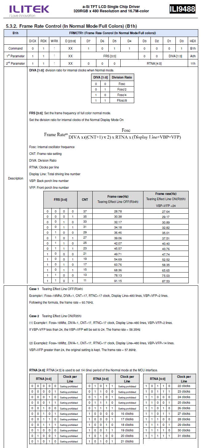
Formula for 9341 driver:
  K = total_driving_line_number + back_porch_line_number + front_porch_line_number = 480 + 2 + 2 = 484
  frame rate = oscillator_frequency / ( clocks_per_line * division_ratio * K )

This formula is slightly different for the 9488 driver:
  newFactor = ( frame_rate_setting + 1 ) * 2
  frame rate = oscillator_frequency / ( clocks_per_line * division_ratio * K * newFactor )

To get 70Hz frame rate (which is default for 9341 and what the Adafruit library uses):
  oscillator_frequency = 18MHz (based on value given in example)
  division_ratio = 1
  clocks_per_line = 27  // Adafruit 9341 library value

  newFactor = oscillator_frequency / ( clocks_per_line * division_ratio * K * frame rate )
  frame_rate_setting = newFactor / 2 - 1

  newFactor = 18M / ( 27 * 1 * 484 * 70 ) = 19.677
  frame_rate_setting = 8.834

  No such frame_rate_setting exists... more math later, this is one of the combos that yields 70Hz
    frame_rate_setting = 11  // code of 0b1101
    clocks_per_line = 22  // code of 0b10110
Power configurations also changed, but I wasn’t able to make heads or tails of what the ideal values were. I left them unset and hoped whatever it defaulted to was good enough.
Now the only thing that remained to sort out was the color. I tried inverting the colors as I had done last time but this wasn’t the problem.
I then tried using the BGR color mode of the driver instead of RGB, but this also wasn’t the problem.
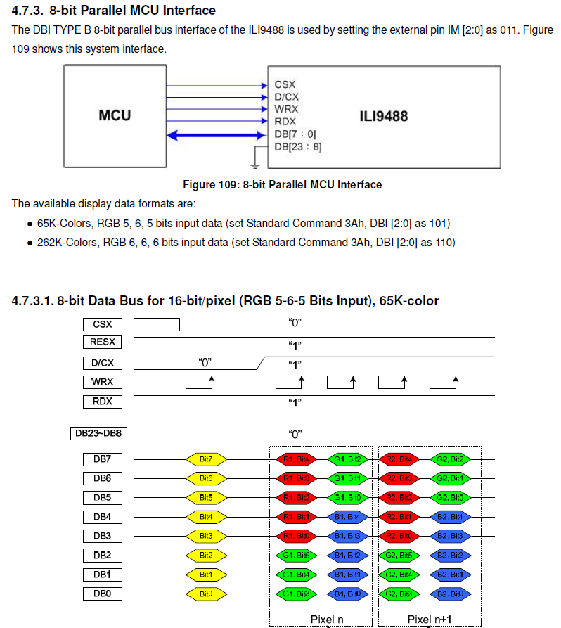
I looked at the display data format section of the datasheet again, and at this point it seemed the most likely culprit.
8-bit mode
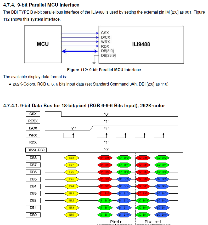
9-bit mode
This became more apparent when I changed the test code to generate single color gradients. Note the blue streaks that appear only when a green gradient is displayed.
void customTest () {

    int w = tft.width();
    int h = tft.height();
    int x, y, c = 0;
    int r, g, b;
    int gradX, gradY, gradX2, gradY2;
    int d = 1;

    for( x = 0; x < w; x += d ){
        for( y = 0; y < h; y += d ) {

            gradX = map( x, 0, w, 0, 32 );
            gradY = map( y, 0, h, 0, 32 );
            gradX2 = map( x, 0, w, 0, 64 );
            gradY2 = map( y, 0, h, 0, 64 );

            // r = gradX;
            // g = 0;
            // b = 0;

            r = 0;
            g = gradX2;
            b = 0;

            // r = 0;
            // g = 0;
            // b = gradX;

            // 565 RGB
            c = ( r << 11 ) | ( g << 5 ) | b;

            tft.drawPixel( x, y, c );
        }
    }
}
In the Adafruit library, color is sent to the driver with the assumption that it is running in 8-bit parallel mode. Therefore it is encoded in RGB 565 format (5 bits to represent red, 6 for green, and 5 for blue) by the following function:
// Pass 8-bit (each) R,G,B, get back 16-bit packed color
uint16_t Adafruit_TFTLCD::color565(uint8_t r, uint8_t g, uint8_t b) {
  return ((r & 0xF8) << 8) | ((g & 0xFC) << 3) | (b >> 3);
}
If the driver is not running in 8-bit parallel mode, then the color data it receives will be incorrectly encoded.
I wrote some JavaScript code to simulate how the 565 color data would be rendered were it to be read by different bit modes. I quickly found a match between what I observed on the LCD and what the simulator predicted would be rendered by a 9-bit parallel configuration. I tested other configurations to be safe, and 9-bit was the only one that produced an identical match.
In the previous snapshot from the datasheet, you can see why this happens. In 9-bit parallel mode, the driver expects the color to be encoded as RGB 666 (6 bits each for red, green, blue). Notice in the diagram that the 9-bit mode uses an additional input pin (unlike 8-bit mode and hence 9 bits). This additional pin (labeled DB8 in the diagram) is tied to ground on the PCB and is not available through the breakout pins (the PCB was designed for 8-bit or SPI mode operation).
When it receives RGB 565 data, it interprets it as follows:
// 565 color data
    R4 R3 R2 R1 R0   G5 G4 G3 G2 G1 G0   B4 B3 B2 B1 B0

// 8 bit mode
    D7 D6 D5 D4 D3 D2 D1 D0   D7 D6 D5 D4 D3 D2 D1 D0  // data pins
    R4 R3 R2 R1 R0 G5 G4 G3   G2 G1 G0 B4 B3 B2 B1 B0  // 565 color data

    Interpreted as,
        r -> R4 R3 R2 R1 R0
        g -> G5 G4 G3 G2 G1 G0
        b -> B4 B3 B2 B1 B0

// 9 bit mode
    D8 D7 D6 D5 D4 D3 D2 D1 D0   D8 D7 D6 D5 D4 D3 D2 D1 D0  // data pins
    00 R4 R3 R2 R1 R0 G5 G4 G3   00 G2 G1 G0 B4 B3 B2 B1 B0  // 565 color data

    Interpreted as,
        r -> 00 R4 R3 R2 R1 R0
        g -> G5 G4 G3 00 G2 G1
        b -> G0 B4 B3 B2 B1 B0
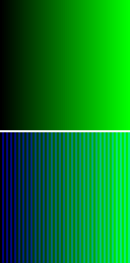
Output from the simulation confirms this hypothesis. In the images below, the top gradient shows the expected result (i.e. when the colors are interpreted as 8-bit) and the bottom shows what is rendered when the colors are interpreted as 9-bit.
G0 B4 B3 B2 B1 B0 In 9-bit mode, the last bit of green is interpreted as the most significant bit of blue. If the last bit of green is zero, darker shades of blue render. Otherwise, lighter shades of blue render.
blue gradient with G0 = 0
![]()
blue gradient with G0 = 1

Combining the two shows the full spectrum available in 9-bit mode

00 R4 R3 R2 R1 R0 Red renders darker shades because its most significant bit is always zero (due to data pin 8 being pulled to ground).
red gradient

G5 G4 G3 00 G2 G1 For green, the effect of the incorrect bit mode is more apparent. Blue streaks appear on every other line because the last bit of green is interpreted as the most significant bit of blue.
green gradient
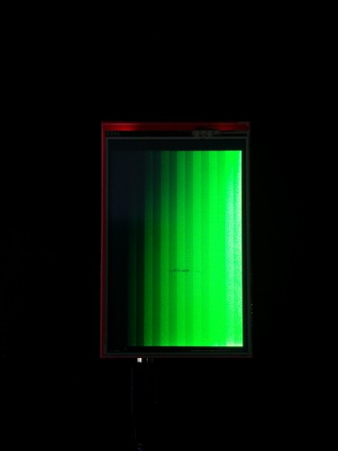
Additionally, notice that the third bit of green will always be zero. This is because it is sampled from data pin 8 which is pulled to ground. This creates the banding visible in the picture below. In the picture, the last bit of green has been set to zero to get rid of the blue streaks and emphasize this secondary effect.
green gradient with G0 = 0
![]()
Stalemate
Data pin 8 is inaccessible and tied to ground, yet the data mode selected is 9-bit.
This is problematic because it means that the third bit of green will always be tied to zero. This restricts the available shades of green to GGG0GG. Further, since the last bit of green is interpreted as the first bit of blue, the last bit of green must be set to zero to prevent blue streaks. This further restricts the available shades of green to GGG0G0. In other words, it makes the LCD assembly completely useless for rendering greens. (Only 16 of the 64 possible shades meet the criteria).
Here is the temporary adjustment I made to the drawPixel function. It works only if you don’t mind the limited palette.
void Adafruit_TFTLCD_mod::drawPixel(int16_t x, int16_t y, uint16_t color) {

    ...

    else if ((driver == ID_9341) || (driver == ID_HX8357D)) {

        setAddrWindow(x, y, _width-1, _height-1);
        CS_ACTIVE;
        CD_COMMAND;
        write8(0x2C);
        CD_DATA;
        // write8(color >> 8);
        // write8(color);

        int r = color & 0b1111100000000000;
        int g = color & 0b0000011111100000;
        int b = color & 0b0000000000011111;

        /*
            Encodes 8-bit color data for use by 9-bit mode

            // 8 bit mode
                D7 D6 D5 D4 D3 D2 D1 D0   D7 D6 D5 D4 D3 D2 D1 D0  // data pins
                R4 R3 R2 R1 R0 G5 G4 G3   G1 G0 00 B4 B3 B2 B1 B0  // 565 color data


            // 9 bit mode
                D8 D7 D6 D5 D4 D3 D2 D1 D0   D8 D7 D6 D5 D4 D3 D2 D1 D0  // data pins
                00 R4 R3 R2 R1 R0 G5 G4 G3   00 G1 G0 00 B4 B3 B2 B1 B0  // 565 color data

                Interpreted as,
                    r -> 00 R4 R3 R2 R1 R0
                    g -> G5 G4 G3 00 G1 G0
                    b -> 00 B4 B3 B2 B1 B0

            Shortcomings:
              . r[5] and g[2] are always set to zero because of the inaccessible D8 pin (that is pulled to ground)
              . b[5] is always set to zero
        */

        write8( ( r | g ) >> 8 );
        write8( ( g << 1 ) | b );
    }

    ...
}
And a picture of the lackluster banded green gradient it produces…
The obvious course of action would be to change the mode to 8-bit. However, the mode selection pins are not broken out onto the PCB.
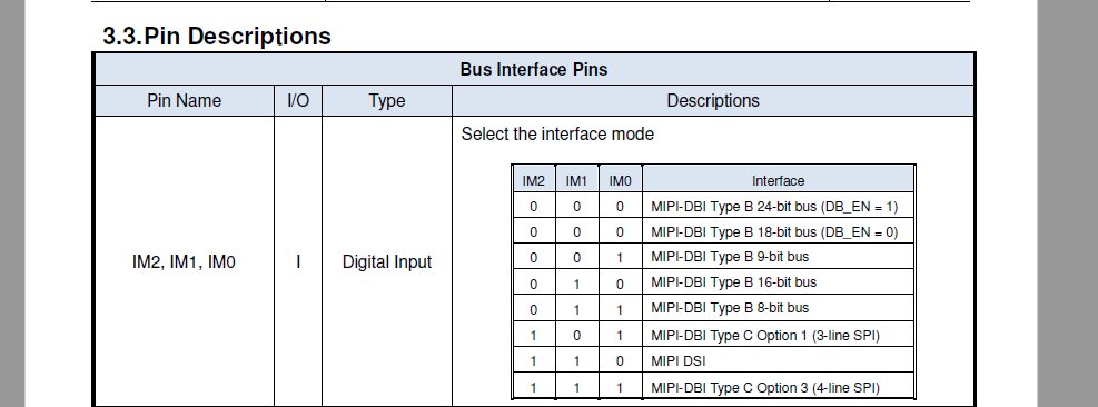
Looking at the datasheet, one sees that driver pins IM2, IM1, and IM0 are used to select the mode where 001 is 9-bit mode and 011 is 8-bit mode.
Changing the mode to 8-bit would require identifying IM1 on the LCD screen’s flex circuit, disconnecting it from ground, and pulling it high instead.
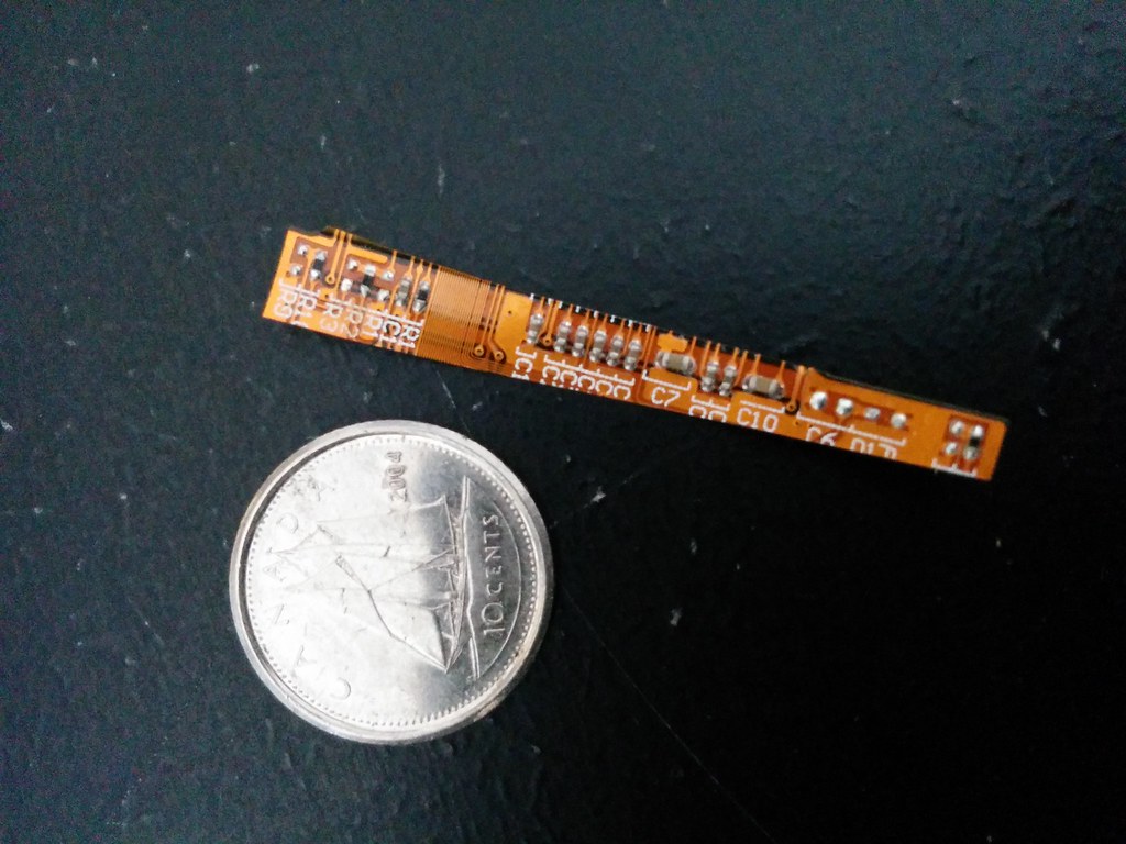
Below is a picture of part of the flex circuit from my previous ‘teardown’. In the picture, that is a dime, not a quarter! Talk about tiny.
Another option would be to find data pin 8 on the flex circuit, disconnect if from ground, and connect it to a jumper wire thus making the pin accessible. In this scenario, the LCD can be used in 9-bit mode.
Both options however require modification of the flex circuit. There is both the challenge of identifying the respective pins on the circuit and of soldering at such a small scale. Though possible and likely a good learning experience, it’s a bit precarious and any number of things could go wrong.
At this point, I’m considering dropping the money for Adafruit’s version and saving this soldering project for another day. Or I could gamble again (plus two months shipping time) on another Ebay LCD.
However all was not a loss. Through this process I learned how TFT LCD drivers work, how to get the necessary information from their datasheets, how the Adafruit library communicates with them, and how to write my own code to communicate with them. This brings me lightyears closer to the goal of writing a VHDL driver for the LCD screen.
Code
*The video is a recent one. I’m not sure why I didn’t take one at the time.