Musings of a Fondue

Games for the Computer

I hope to run some of the games for the PICO-8 fantasy console on my Homebrew Computer. For example,


The developers have spent a lot of time writing the code, designing the graphics and gameplay, and creating the music to make the games beautiful and fun. While they are not as CPU/GPU intensive as your typical AAA titles, it would be quite an achievement if my computer can run them at a decent frame rate!

A VHDL Take on Ben Eater's CPU

IMG_20170903_132332

As part of the Homebrew Computer Project, I have been exploring other CPU architectures and their implementations in order to broaden my understanding of CPU design.

An awesome one that I came across was Ben Eater’s 8-bit computer. It is well documented through a series of videos on Youtube and also on his blog. The architecture is simple which allows you to get a firm understanding of all its components.

Since it is a known working design, I saw it as the perfect opportunity to practice implementing a CPU in VHDL.

LCD Woes - Back With a Vengeance

After months of waiting the new LCD assembly finally arrived!

I noticed the PCB had a different layout than the one I had earlier. Gone was the onboard voltage regulator. Yay cost cutting! Also missing was the ZIF connector. In this one, the LCD flex cable was soldered directly onto the PCB, yay more cost cutting! Given the trouble I had earlier trying to resolder the four chunky traces of the touch screen cable, prospects looked dim for resoldering the many small traces of the LCD screen cable. Drilling mounting holes onto the PCB no longer looked like an option.

Before doing anything, I checked whether the LCD works. I connected it to an Arduino and loaded Adafruit’s graphics test. It sort of worked. But not quite. The screen flickered and what rendered looked glitchy. See the video* below for what I mean. Contrast this with what the test is supposed to look like.

Not quite right

LCD Woes

IMG_20170501_153234

It was time to put the previously disassembled LCD assembly back together. Reconnecting the LCD to the PCB was easy enough (given that it was a ZIF connector). However reconnecting the touch screen would prove to be my undoing.

Designing a Case

I had a hard time figuring out how to mount the LCD assembly. It was designed for use as an Arduino shield and thus its PCB had no mounting holes. I wanted a solution that was sturdy but non-permanent so things like glue were not options. I came across these clips from Adafruit, but they didn’t seem rugged enough to support the handling the touch screen (and hopefully handheld computer) was going to receive.

RAM for the Computer

IMG_20170130_162235

Internal RAM

My original plan was to use the FPGA for RAM, either by building the RAM in VHDL using flip flops or by using the FPGA’s dedicated RAM blocks.

Learning VHDL - VGA

Next in line in the awesome tutorial series from Nandland was VGA. I didn’t have a VGA connector for my FPGA, but wondered if I could jury-rig something with what I had on hand.

The wiring diagram below from Grant Seale’s Multicomp gave me a very good idea on how to go about it.

In the Nandland tutorial (image below), three signals are used per channel instead of two so my setup reflects that.

I had five 1Kohm resistors on hand, enough to control one channel. I used two of them in parallel to get the 500 ohms (close enough to 549), two in series to get the 2K ohms, and one on its own for the 1K ohms. Jumper wires were used to connect to the pins (red, green, blue, hsync, vsync). Luckily, all the ground pins were in-line (and the random pin in-between was an unused pin) so I just tied the whole line to ground using one wire (instead of several jumper wires). Here is the final masterpiece:

IMG_20170124_121927

And the overall setup:

IMG_20170124_124112

Learning Shaders 2

Here are some additional resources I’ve come across for learning shaders.

Book of Shaders

Great resource because it starts from the absolute basics and builds up, rather than skipping to all the fancy stuff. Emphasis is placed on understanding the fundamentals and developing an intuitive understanding of how things work.

Lighthouse3D

Good introduction to lighting. The tutorials are based on OpenGL but can be adapted to Three.js (which is what I used to follow along). Here’s a toon shader I made from one of the lessons (click image for animation):

Shader School

I think it’s a bit useless to work through this one if you do not have prior exposure to GLSL. But once you do, it’s an awesome series. There’s even a section that touches on using the GPU for general purpose computing.

WebGL Workshop

It is intended to be taken after Shader School. The course teaches you how WebGL (based on OpenGL) works. Basically all the stuff libraries like Three.js do on your behalf. Even if you don’t intend to write your applications using raw WebGL it is useful to understand what is happening behind the scenes.

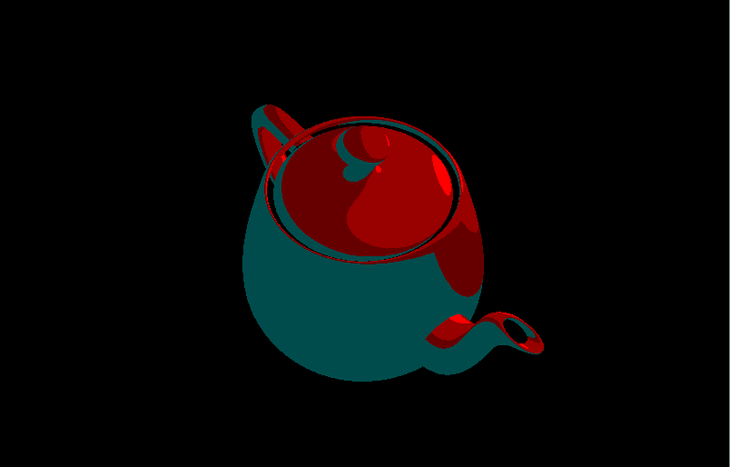
A neat trick I learned from the course was discard. You can either render a pixel (default) or specify that it be ‘discarded’ (i.e. skipped). Here is a slicing effect I made using this (click image for animation):
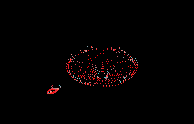
Interactive 3D Graphics

Though not strictly a shader focused course, it covers so many fundamental concepts with regards to 3D graphics that skipping it would be doing yourself a disservice. The course is taught using Three.js and touches on pretty much everything you need to know about how 3D computer graphics work and how to create them.


Sidenote: The demos above build on this official Three.js example. The teapot geometry used can be found here and comes from the Interactive 3D Graphics course.

Learning VHDL

I chose to use VHDL to program the FPGA because it is closer to a schematic representation than Verilog. Verilog seems (to me) like learning a new programming language whereas VHDL is more like describing the circuit.

For example, take the construction of a full adder. Here is a video of the structure generated by my code below:

An ADC for the Computer

I bought an analog to digital converter for the computer.

IMG_20160831_154310

The FPGA can only process digital signals (on or off, 3.3V or 0V) but the touch screen outputs analog signals (values ranging from 3.3V to 0V each representing a relative position).

It was my first time soldering (the header pins). As you can see, all the flux was used.

A Keyboard for the Computer

Much like Charles’s hardware setup (see a pattern here?), I decided to use part of the touch screen as the keyboard for the computer.

Design

I roughed out the design using Inkscape. (Because unlike Photoshop or Gimp, you can easily move and resize shapes around after creating them).

I then recreated the design using JavaScript. I used Khan Academy’s coding environment* to do this because its live update feature made iteration and tweaking a breeze. Converting the Inkscape design to code using the Arduino IDE would have been a tedious process as I would have had to upload the sketch each time I wanted to see the effect of a change made.

In the JavaScript code, I used only basic functions that are supported by the Adafruit Graphics Library such as drawRect, drawText, and fillColor. The color scheme is based on this palette with tweaks here and there.

Below is the Javascript mockup. Try typing. Clicking the up arrow toggles the keyboard’s style.

Non-volatile Memory for the Computer

I’m looking at the SD card reader attached to the Mcufriend LCD shield… and thinking it can act as the non-volatile memory for the Hack computer.

When used with the Arduino SD Library, one can easily read, write, create, and remove files (and directories).

The SD card solution is also very convenient! You can plug the SD card into any regular computer (or phone) and copy onto it any programs you want to run on the Hack Computer (for example these games on Github). (Think game cartridge or USB thumb drive). Similarly, if you write a program and save it onto the SD card when using the Hack Computer, you can then open it up later on any other computer (or phone).

An FPGA for the Computer

I’ll be using the Altera Cyclone II - Mini Development Board as the main FPGA of the Hack Computer V1 (name pending).

Cyclone II Mini Dev Board

I got it for $20 on eBay and the kit came with a (knockoff) USB Blaster for programming. The idea to use the board came from Charles Cole’s hardware setup of his homebrew Z-Machine. The price is great and I love that it only has the bare minimum components on it.

I worked through this excellent getting started guide by Trey Dahlberg on Youtube and everything seems to be running well.

Specs:

  • Altera Cyclone II EP2C5T144C8
  • 50MHz clock
  • Schematic

Update (January 18, 2017):

I recently came across the Multicomp project by Grant Searle. In it he uses this development board and consequentially has a ton of really helpful information on the board and some of the things it’s capable of. The project is described by Hackaday as a ‘pick and mix retrocomputer’ which allows you to use the FPGA as a Z80, 6502, 6800 or whatever CPU mashup you feel inspired to. His project also describes in detail interfacing with various devices including SRAM, SD cards, VGA, composite video, PS/2, USB - basically I found the holy grail! Check out the project page to learn more about the board, and maybe even build a mix and match computer of your own.

Note: if you use this development board, make sure to desolder the four zero ohm resistors as explained in Grant’s project page.

A Screen for the Computer

I bought this Mcufriend touch screen. It’s the unbranded version of this one sold by Adafruit.

Front

Back

I got it for $10 compared to Adafruit’s price of $40. I came across the screen through this awesome video by Charles Cole where he walks through his FPGA implementation of a Z-Machine. I also bought the Altera mini dev board he recommends ($20 which is a steal) but that’s another post.

My gameplan is

  • To first get it working on Arduino (since there is information available online on how to do so).
  • Once it works on Arduino, convert the relevant files (driver, graphics) from C, Python, or whichever language is used to Hack Computer’s high level language.
  • Then change a few things here and there on the Hack Computer so that it outputs for the LCD screen instead of Tkinter.

Part 1) Getting the screen to work

Particles and SketchUp Shenanigans

Particles are cool! Example,

I had this idea back in 2014 of getting the points from premade 3D models (similar to the video above), and using them to do fancy animations in Threejs. Then I hit a knowledge wall and shelved it. Until today…

Nand to Tetris - Part 1 of 2

I finished the first half of the course.

And here’s a video of what my implementation looks like in action.

It can run programs! Albeit very slowly. The demo above is vastly sped up. In realtime, it took about 37 minutes to run.

The code for the emulator is on Github.